Chapter 2 PXI-1006 Features
PXI-1006 User Manual 2-8 ni.com
Using the Power Monitoring Feature
You can use a digital voltmeter to ensure all voltage levels in your
PXI-1006 are within the allowable limits.
Caution
When connecting digital voltmeter probes to the rear D-sub connector, be careful
not to short the probe leads together. Doing so could damage the power supply.
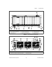
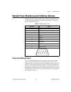
Referring to Table 2-2, connect one lead of the voltmeter to a supply pin on
the remote power monitoring connector (9-pin D-sub) on the rear panel.
Refer to Table 2-1 for a pinout diagram of the remote power monitoring
connector. Connect the reference lead of the voltmeter to one of the ground
pins. Compare each voltage reading to the values listed in Table 2-2.
Note
Use the rear-panel D-sub connector tocheck voltages only. Do not use theconnector
to supply power to external devices.
If thevoltages fallwithin the specified ranges,the chassis complies withthe
CompactPCI voltage limit specifications. Notice that the rear-panel D-sub
connector is to be used to check voltages only. Do not use these voltages to
supply power to external devices.
Note
If the fans or power unit fail to function properly, refer to Chapter 3,
Troubleshooting.
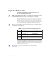
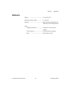
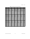
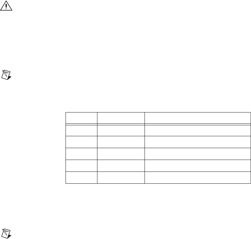
Table 2-2. Power Supply Voltages at Power Monitoring Connector (DB-9)
Pin Supply Acceptable Voltage Range
2 +5 V 4.75 to 5.25 V
4 +3.3 V 3.135 to 3.465 V
6 +12 V 11.4 to 12.6 V
8 –12 V –12.6 to –11.4 V
1, 9 Logic Ground N/A