


Contents
How to install the stand on your washing
machine _ _ _ _ _ _ _ _ _ _ _ _ _ _ _ _ _ _ _ _ _ 2
How to install the stand on your tumble dryer _ _ _ _ 4
Subject to change without notice
How to install the stand on your washing machine
Warning! Do not install the stand on a washer/dryer
column.
Caution! If the washing machine is already
connected to the mains, proceed as follows:
1. pull out the plug from the mains;
2. stop water supply by closing the tap;
3. disconnect the inlet pipe and the drain pipe and get
ready to collect any water left in the machine with a
shallow basin.
Important! With a brand new washing machine, do as
follows:
1. install the stand before connecting the machine to
water and electricity mains;
2. follow the instructions to remove any transport safety
equipment.
Before you start installing the stand on your washing ma-
chine make sure you have plenty of room. Avoid working
in restricted spaces as the installation and subsequent
adjustment operations may turn out quite awkward and
difficult to carry out.
Take the stand out of its package and use the cardboard
to rest washing machine and stand on, so you wont
scratch the equipment varnish and the floor.
In the stands drawer you will find an envelope with all the
necessary material for a correct assembly.
Have ready a Phillips screwdriver to fit rear brackets to
the stand and to fit rear brackets to the machine.
The pack includes:
• 4 front rubber feet (for tumble dryer only);
• 6 rear metal brackets (4 for washing machine and, de-
pending on the model, 2 for tumble dryer);
• 6 self-tapping screws (4.2 x 13 mm);
• 1 key to adjust stand feet.
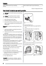
Important! Before starting the installation, adjust the
stand's feet in order to achieve a perfectly stable hori-
zontal position.
fig. 1
Proceed as follows (fig. 1):
• loosen the nuts using the key supplied with the
stand;
• adjust the feet to allow for an uneven floor;
• tighten up all check nuts.
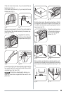
fig. 2 fig. 3
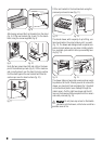
Before picking the rear brackets you must first look at
the machines side (fig. 2 and 3).
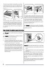
fig. 4
fig. 5
2