


15, 30, & 60 cfm Compact Dryers 27
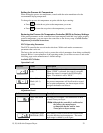
4. If either the left or right bed safety temperature switch opens, a regen heater fault is
generated. “HIGH TEMP” is displayed on the relay screen. The alarm light is
activated.
5. If the process temperature controller faults or the process heater safety switch opens,
a heater fault is generated. “HIGH TEMP” is displayed on the relay screen. The
alarm light is activated. The process heater, regen heater, and process/regen blower
are turned off. (Requires turning the dryer OFF).
6. If the process blower overloads trips, a process blower fault is generated. “PROC
BLWR” is displayed on the relay screen. The alarm light is activated. The process
heater, regen heater, and process/regen blower are turned off (3 phase only).
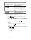
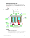
7. The valve position limit switch enables the right bed heater and provides an input
signal to the programmable relay when actuated by the cam lobe. When the cam
verifies position is high, the right bed is activated. When the cam verifies position is
low, the left bed is activated. Each heater is ON-OFF controlled.
8. Upon completion of the HEAT portion of the regeneration sequence, the regen
heaters are disabled by the programmable relay and the COOL time begins.
9. Once the Cool time has expired, the valve motor is turned on until the cam switch
makes a transition. Upon making a transition, the timing sequence is restarted for the
new bed.
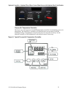
10. When no fault conditions exist, the display reads “SYSTEM NORMAL”.
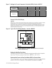
11. The top 2 lines of the display show the HEAT and COOL times (in minutes) for the
regeneration sequence. Changes to these times can be made by the operator as
follows:
a. Press the up or down arrow until the cursor is positioned at the number to be
changed.
b. Press the “+” key to increment the number, or the “-“ key to decrement the
number.
c. Press the “OK” key to accept the value and write to the relay memory.
OR
d. Press the “ESC” key to cancel the changes.
Note: A change will NOT take effect until step 12-c is done.
12. The dryer is shut off by turning the control power switch to the OFF position.
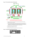
13. Refer to Schematic drawing enclosed in the control enclosure.
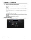
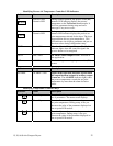
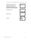
Alarm Display Messages
Note: The relay screen which contains the Alarm Display Messages is located
inside the controller enclosure.
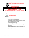
WARNING! Do not attempt to check the Alarms on the Controller located within the
unit enclosure unless you are a qualified electrician!