


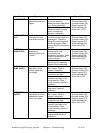
22. Two-hand control is not required or provided.
23. All dryers and conveying equipment should be moved around and set in a place
with a lift truck or equivalent.
24. There are no frequent repetitive cycles that require manual control⎯repetitive
functions are automatic while the drying and conveying system is operating.
25. An inspection report detailing the functional test is included with the dryer and
conveying system.
26. The machine is not equipped with cable less controls.
27. Color-coded (harmonized) power cord is sufficient for proper installation.
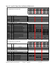
Aftercooler Design Specifications
Entering water temp.
ºF ºC
85ºF
50°F (If used as Plasticizer trap)
29ºC
10°C (If used as Plasticizer trap)
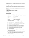
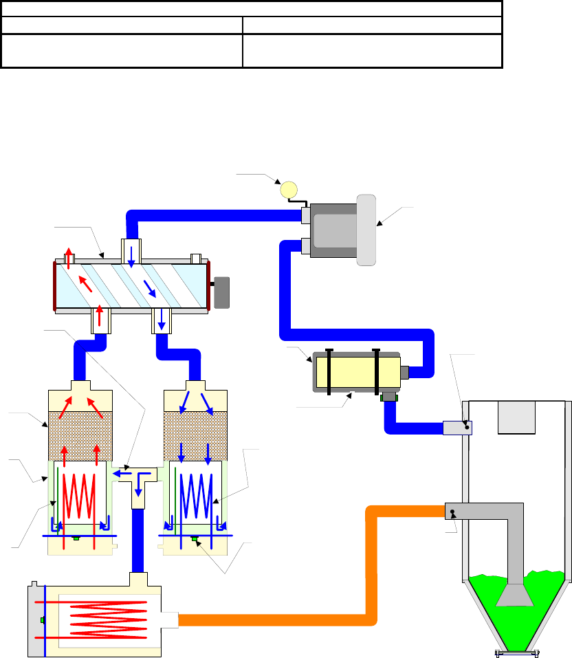
7-4 Drawings and Diagrams
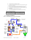
Figure 12: Standard Model (180°F to 250°F) Air Flow Schematic
Utilizing -40F dew
point air to regenerate
and cool the
desiccant.
Double wall
constructed heater
housing and
desiccant
container.
Low watt density
heaters, can
operate safely
with minimum air
flow.
Regeneration
thermocouple,
monitors and
controls the
regeneration
temperature
Pressure switch, makes
sure the blower is
functioning correctly.
High
temperature
snap switches,
monitor the heat
status of the
heater housings.
High pressure peripheral
regenerative blower.
Insulated
stainless steel
drying hopper
2-1/2” Hose
2-1/2” Hose
Dryer valve
13X Molecular
Sieve 8x12
beads.
2”
Hose
2”
Hose
2”
Hose
2” Hose
Process /
Regeneration
Air Filter
Process Air
Temperature
Thermocouple
Position
Return Air
Temperature
Thermocouple
Position
Make-Up
Air
Portable Drying/Conveying Systems Chapter 7: Appendix 57 of 63