


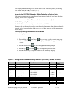
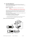
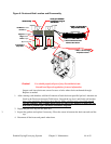

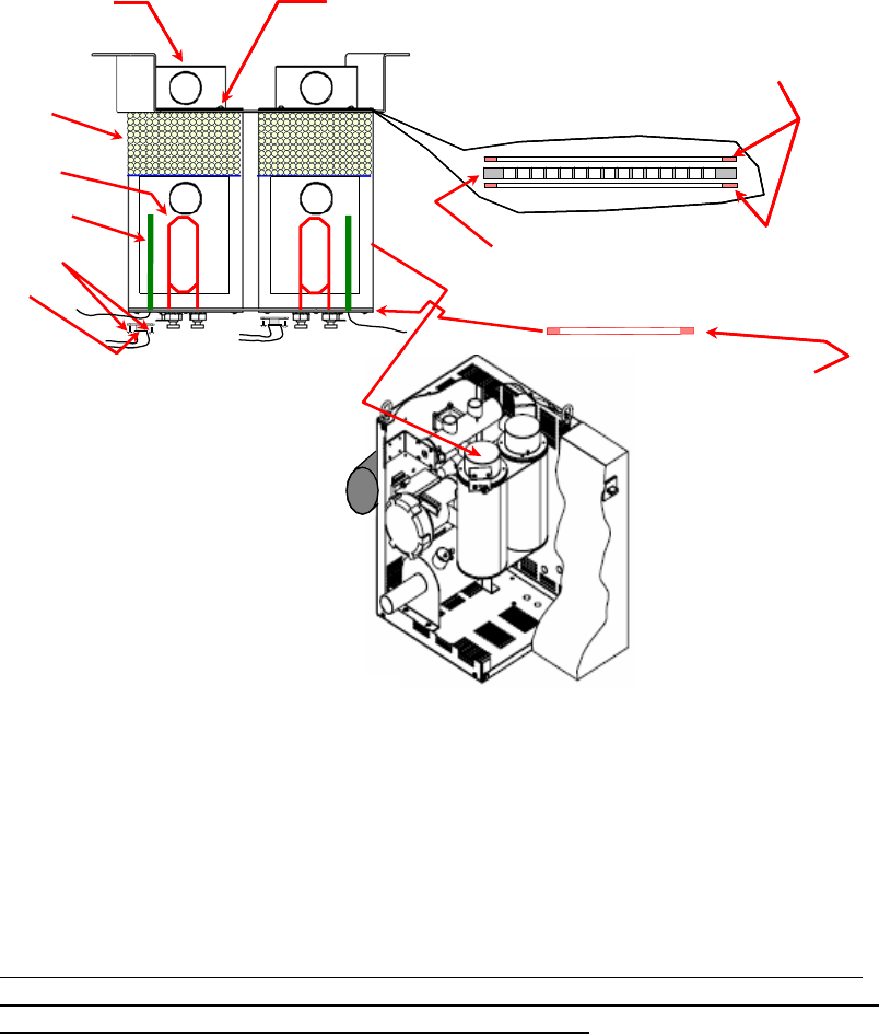
Figure 8: Desiccant Bed Location and Disassembly
Undo (4) 10-32 Button
Head Screws using 1/8
Allen Wrench
Desiccant Cap
1" Wide x 1/8" Thick Silicon
Strip and Stick Gasket
16 Mesh 0.028 Diameter Wire
Stainless Steel Screen
(2) 4-40 screws
Hi Temperature
Snap Switch
Regeneration Heater
1" Wide x 1/8" Thick High
Temperature Gasket
Regeneration
Thermocouple
13X Molecular Sieve
8x12 Beads
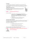
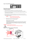
Undo (4) 10-32 Button
Head Screws using 1/8
Allen Wrench
Desiccant Cap
1" Wide x 1/8" Thick Silicon
Strip and Stick Gasket
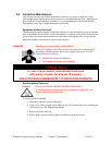
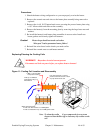
Undo (4) 10-32 Button
Head Screws using 1/8
Allen Wrench
Desiccant Cap
1" Wide x 1/8" Thick Silicon
Strip and Stick Gasket
16 Mesh 0.028 Diameter Wire
Stainless Steel Screen
(2) 4-40 screws
Hi Temperature
Snap Switch
Regeneration Heater
1" Wide x 1/8" Thick High
Temperature Gasket
Regeneration
Thermocouple
13X Molecular Sieve
8x12 Beads
Caution! You should properly dispose of any discarded desiccant.
Consult local disposal regulations for more information.
Inspect each lower desiccant screen for tears or holes where desiccant burned-through.
Replace as needed.
1. After cleaning each chamber, add the full amount of bead desiccant specified per bed. Amounts are
listed in the Desiccant Amounts Table below. Smooth the top level, and finally add another
layer of the remaining bead desiccant to the top. Make sure this layer is level and smooth.
Tap the chambers with a rubber melet gently for one or two minutes to make sure the
desiccant is packed tight. Add more desiccant if required.
2. Repeat the previous step for the other bed.
3. 3. Inspect the gaskets and replace if necessary. Place the screen in between the desiccant tank and the
cap.
4. Reconnect all the hoses and panels when done.
Portable Drying/Conveying Systems Chapter 5: Maintenance 44 of 63