


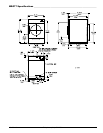


113430-10 Telephone: (641) 787-7000 21
!
!
Warning (CE Dryers)
This appliance must only be operated with the gas
type indicated on the dryer’s data plate. If the
appliance is converted (gas type changed), a data plate
amendment must be obtained from Maytag.
Conversions done improperly can result in a fire or
explosion!
Gas Pressure Testing _________________
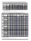
For proper operation, the gas pressure must be correct,
consistent and maintained at the gas pressure rates shown
on page 18. Provisions are made at the gas valve for taking
gas pressure readings.
There are 2 types of devices used to measure gas pressure.
They are the spring/mechanical type gauge and the
manometer. The use of the spring/mechanical type gauge is
not recommended because they are very easily damaged
and are not always accurate. The preferred type of gauge is
the manometer because it is a simple device to use and is
highly accurate. A manometer is simply a glass or transparent
plastic tube with a scale graduated in inches or mb. When it
is filled with water and pressure is applied, the water in the
tube rises, showing the exact gas pressure.
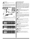
Gas Pressure Test Procedure
Turn gas cock in gas supply line to “OFF” position.
50 Hz dryers: Back out miniature screw inside pressure tap
and attach manometer (refer to the illustration on page 20).
60 Hz dryers: Install pressure tap and attach manometer (refer
to the illustration on page 20).
Turn gas cock to “ON” position.
Start the dryer in Heat Mode and wait for ignition. Gas manifold
pressure should be as shown on page 18.
If the gas pressure needs to be adjusted, refer to “Gas
Pressure Adjustment” on this page.
Once test is complete, turn gas cock to “OFF” position.
Remove manometer. Tighten screw inside the pressure tap
or install plug.
Turn gas cock to “ON” position and check for leaks with soap
solution with main burner “ON.”
Water Information _____________________
Before You Start
Check Local Codes and Permits
Call your local water company or the proper municipal
authority for information regarding local codes.
Important
It is your responsibility to have all plumbing
connections made by a qualified professional to
ensure that the plumbing installation is adequate and
conforms to local, state, and federal regulations or codes.
It is the installer’s or owner’s responsibility to see that the
required water pressure, pipe size, or connections are
provided. The manufacturer assumes no responsibility if
the fire suppression system is not connected, installed, or
maintained properly.
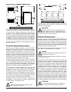
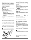
• Converting from unregulated L.P. to unregulated
natural gas: no change to the regulator is required.
• Converting from regulated L.P. to regulated natural gas:
remove the white plastic regulator adjustment screw
(under vent cap). Remove spring under screw and
replace with spring from kit (P/N 140415). Replace
regulator adjustment screw.
Install the gas train back into the dryer gas train enclosure.
Be sure the tab at the rear of the gas train engages into the
mounting slot.
Connect the union and the 3 electrical plugs.
Open all shutoff valves, reconnect electrical power to the dryer,
and test for leaks.
Operate the dryer through 1 complete cycle to ensure proper
operation.
With dryer operating, check the manifold (burner) pressure
at the tap on the gas valve to ensure proper operating pressure
(refer to chart on page 18).
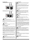
Gas Pressure Adjustment
Disconnect electrical power to the dryer.
Important
The MDG51 and MDG77 will require that the
following procedures be performed on both
burner assemblies.
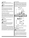
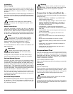
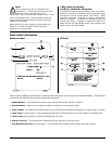
To adjust gas valve’s internal regulator, remove the regulator
vent cap with the regulator adjustment tool, which is located
on the back guard between the gas inlet and exhaust outlet
(refer to the illustration below for proper use of adjustment
tool). Be sure to use one of the wide ends of the adjustment
tool for removal of the vent cap. Once vent cap is removed,
the narrow end of the adjustment tool can be used to turn the
plastic adjustment screw in the valve. Turn the screw
clockwise to raise pressure and counterclockwise to lower
pressure.
Gas (burner) pressures are measured with the burner in
operation for all burner adjustment conditions. Therefore
once the necessary adjustments have been made, the dryer
must be operated in a heating cycle to verify that the pressure
is correct. If it is not correct, you must discontinue the power
to the unit and make further adjustments. Repeat these steps
as many times as necessary to achieve the correct burner
pressure. Once the adjustment of the valve is complete, the
vent cap must be replaced and sealed with, for example,
paint to prevent maladjustment by the user.
Edge #1 for vent cap
Edge #2 for adjustment screw
!