


16 Maytag Co. 113430-10
Grounding
A ground (earth) connection must be provided and installed
in accordance with local, state, and national regulations or
codes of the country of origin. In the absence of these codes,
grounding must conform to applicable requirements of the
National Electrical Code ANSI/NFPA NO. 70-LATEST EDITION,
or in Canada, the installation must conform to applicable
Canada Standards: Canadian Electrical Codes Parts 1 & 2
CSA C22.1-1990 or LATEST EDITION. The ground connection
may be to a proven earth ground at the location service panel.
For added personal safety, when possible, it is suggested
that a separate ground wire (size per local codes) be
connected from the ground connection of the dryer to a
grounded cold water pipe. Do not ground to a gas pipe or hot
water pipe. The grounded cold water pipe must have
metal-to-metal connection all the way to the electrical ground.
If there are any nonmetallic interruptions, such as, a meter,
pump, plastic, rubber, or other insulating connectors, they
must be jumped out with a wire (size per local codes) and
securely clamped to bare metal at both ends.
Important
For personal safety and proper operation, the dryer
must be grounded.
Provisions are made for ground connection in each dryer at
the electrical service connection area.
Warning
Electrical Grounding Instructions – This dryer is
equipped with a 3-prong (grounding) plug for your
protection against shock hazard and should be plugged
directly into a properly grounded 3-prong receptacle. Do
not cut or remove the grounding prong from this plug.
Electrical Connections
A wiring diagram is located behind the control panel for
connection data.
If local codes permit, power to the dryer can be made by the
use of a flexible UL listed power cord/pigtail (wire size must
conform to rating of dryer), or the dryer can be hard wired
directly to the service breaker panel. In both cases, a strain
relief must be installed where the wiring enters the dryer.
For CE Models Only
The means for disconnection from the supply must be
incorporated into wiring having a minimum contact separation
of 3.0 mm in all poles.
Single-Phase (1ø)
Wiring Connections/Hookup
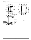
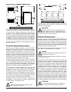
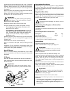
The electrical input connections are made into the rear service
box located at the upper right area of the dryer. The ground
connection is made to the copper lug, also provided in this
box. To gain access, the service box cover must be removed.
!
!
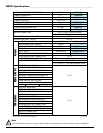
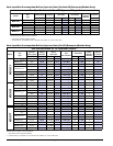
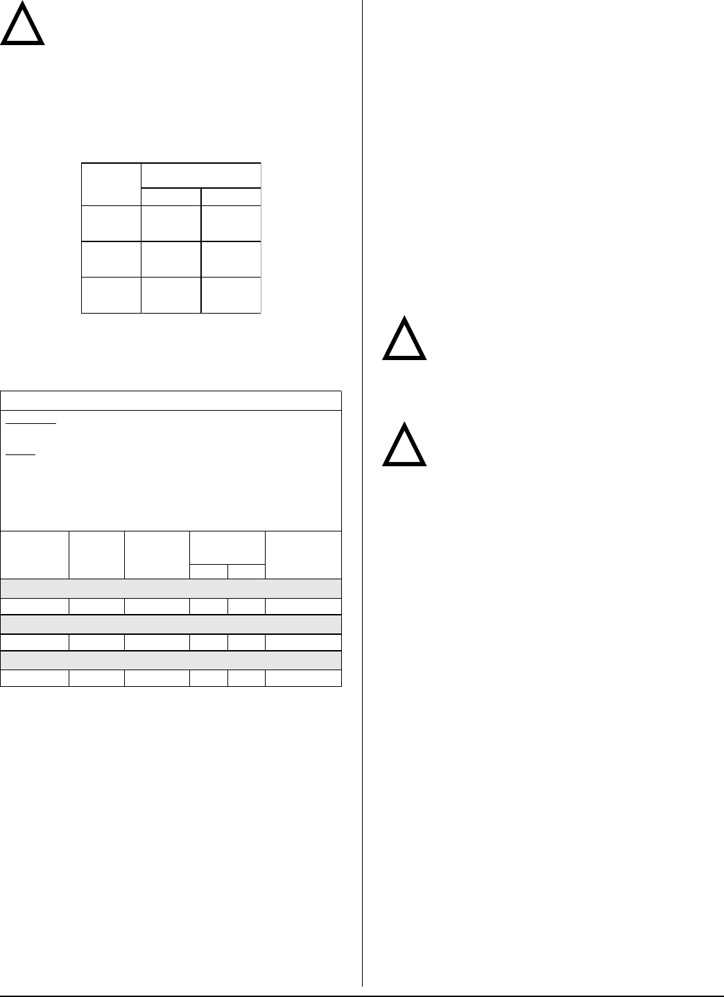
ELECTRICAL SERVICE SPECIFICATIONS
IMPORTANT:
NOTES
: A.
B.
C.
208 VAC AND 230/240 VAC ARE NOT THE SAME. When ordering,
specify exact voltage.
When fuses are used they must be dual element, time delay, current
limiting, class RK1 or RK5 ONLY. Calculate/determine correct fuse
value, by applying either local and/or National Electrical Codes to
listed appliance amp draw data.
Circuit breakers are thermal-magnetic (industrial) motor curve type
ONLY. For others, calculate/verify correct breaker size according to
appliance amp draw rating and type of breaker used.
Circuit breakers for 3-phase (3ø) dryers must be 3-pole type.
SERVICE
VOLTAGE
PHASE
WIRE
SERVICE
APPROX.
AMP DRAW
CIRCUIT
BREAKER
60 Hz 50 Hz
MDG31
120 1ø 2 10.3 — 15
MDG51
120 1ø 2 15.6 — 20
MDG77
120 1ø 2 15.6 — 20
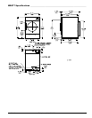
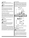
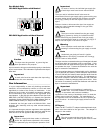
Warning (Gas Models Only)
Dryers built for use with a voltage between 200
and 240 must verify the input voltage during
installation. If the nominal voltage is outside of the
medium tolerances shown on the diagram below, adjust
the autotransformer, located near the burner assembly. To
adjust the autotransformer wiring, place the red wire on the
appropriate tap (HIGH, MED, LOW) of the autotransformer.
For additional wiring details, refer to the electrical diagram
located on the inside of the control panel.
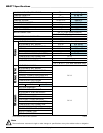
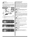
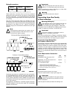
Electrical Service Specifications
Gas Models Only
!
TERM
LINE VOLTAGE
50 Hz 60 Hz
HIGH
260
226
283
249
MED
239
208
260
230
LOW
217
189
236
208
12/18/08