


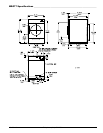
20 Maytag Co. 113430-10
!
!
!
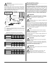
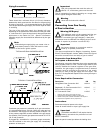
Unregulated Gas Valve
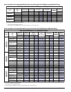
Regulate (govern) gas externally (refer to “Supply Pressure”
in chart on page 18) to the correct gas pressure for the gas
being used. Operate dryer through 1 complete cycle to ensure
proper operation.
Regulated Gas Valve
Refer to “Gas Pressure Adjustment” on the following page to
adjust the gas valve to the appropriate burner pressure listed
on page 18. The supply pressure must also match what is
listed on page 18 for the type of gas to be used.
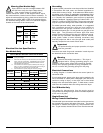
Important
Conversions done improperly can result in a fire or
explosion!
Conversion from Propane or Butane Gas
to Natural Gas
The following conversion allows the dryer to be operated with
natural gas.
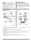
Parts Required for Conversion:
Description P/N Qty
Vent Cap and Spring 140415 **
Burner Orifice (Injector) * **
* Refer to page 18 for orifice (injector) size.
** MDG31 will require 1; MDG51 and MDG77 will require 2.
Instructions
Disconnect electrical power to the dryer.
Close all shutoff valves in dryer’s gas supply line.
Important
The MDG51 and MDG77 will require that the
following procedures be performed on both
burner assemblies.
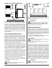
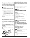
Open the panel located just below the loading door.
Locate the gas train and disconnect the union, 3 electrical
plugs, and the gas train mounting screws from the burner.
Carefully slide the gas train out of the gas train enclosure.
(The carbon ignitor located at the far end of the gas train is
very fragile.)
Remove 2 burner tube mounting screws and remove burner
tube in order to gain access to the orifice.
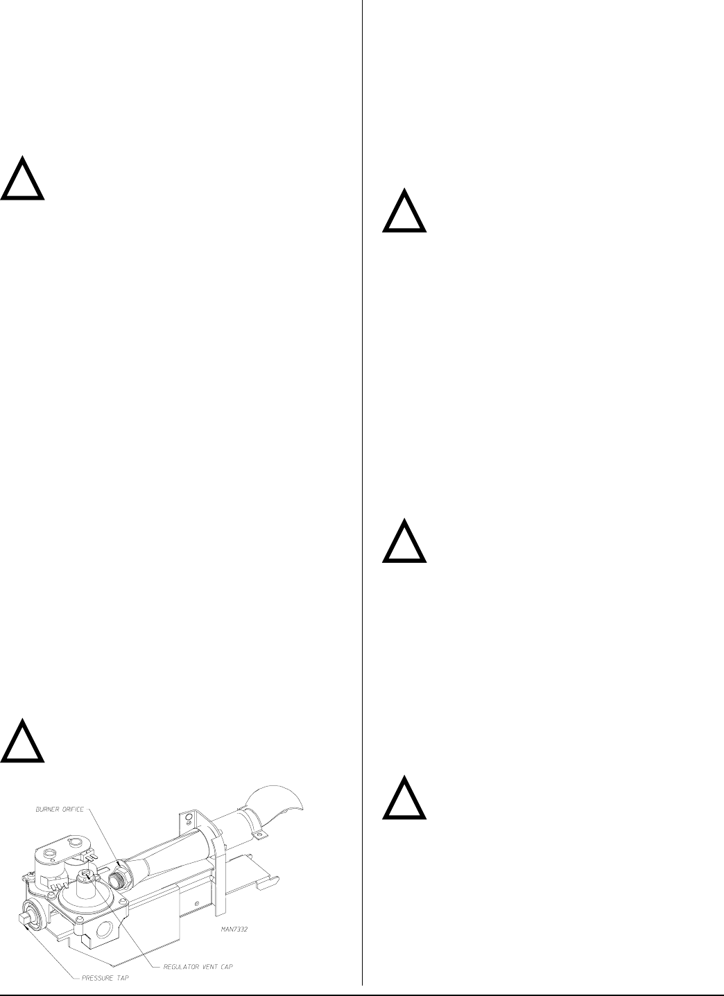
Using a 3/8” wrench or socket, remove the existing orifice
and replace it with an orifice from the kit.
Important
Use extreme care when removing and replacing
orifice (injector). This orifice (injector) is made of
brass, which is easily damaged.
Reinstall the burner tube onto the burner base.
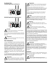
Select from the following 3 options, the conversion to be
performed:
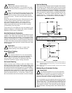
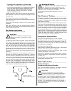
• Converting from unregulated L.P. to regulated natural
gas: use a flat screwdriver to remove the cap with
blocking pin and install the regulator vent cap from the kit
(P/N 140415).
!
!
Locate the gas train and disconnect the union, 3 electrical
plugs, and the gas train mounting screws from the burner.
Carefully slide the gas train out of the gas train enclosure.
(The carbon ignitor located at the far end of the gas train is
very fragile.)
Remove 2 burner tube mounting screws and remove burner
tube in order to gain access to the orifice.
Using a 3/8” wrench or socket, remove the existing orifice
and replace it with an orifice from the kit.
Important
Use extreme care when removing and replacing
orifice (injector). This orifice (injector) is made of
brass, which is easily damaged.
Reinstall the burner tube onto the burner base.
Use a flat screwdriver to remove the regulator vent cap.
• For unregulated L.P. gas (most countries): install
blocking pin (P/N 140414).
• For regulated L.P. gas (some countries): remove the
white plastic regulator adjustment screw (under vent
cap). Remove spring under screw and replace with
spring from kit (P/N 140416). Replace regulator
adjustment screw.
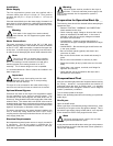
Install the gas train back into the dryer gas train enclosure.
Be sure the tab at the rear of the gas train engages into the
mounting slot.
Connect the union and the 3 electrical plugs.
Affix L.P. Conversion Label (P/N 114515) to the dryer’s data
label.
Complete L.P. Kit Conversion Confirmation Label (P/N
114083) and affix this label as close as possible to the dryer’s
existing dryer rating (data) label/plate.
Non-CE Dryers
Affix L.P. Conversion Rating Label Addendum (P/N 114090)
as close as possible to the dryer’s existing dryer rating (data)
label/plate.
CE Dryers
Affix new data plate label that came with the conversion kit.
Open all shutoff valves, reconnect electrical power to the dryer,
and test for leaks.
Important
Never test for leaks with an open flame!!! Use a
soapy water solution or product intended for that
purpose.