


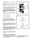

9. Saw a 4',_" hole in floor and position dryer. When exhausting from the side, the installation should be
10. Secure the shortened pipe to the blower housing with a made according to the steps described in BOTTOM
screw at the top and seal all joints with tape or silicone EXHAUSTING and as noted above.
bathtub caulk.
11. Install a 4"90 degree elbow as shown. INDOOR EXHAUSTING
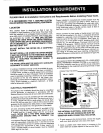
Step #3D showsa typical installationwithindoor exhausting.
Indoor exhausting is not recommended unless the laundry
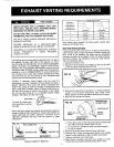
FIG. #7 REPLACESCREW room is large and sufficient cross ventilation is available by
ANDTA_7" 90DEGREEELBOW opening two windows, ora door and a window,or where an
L_ }lil_ 4" DIAl7 exhaust fan is located in the laundry room.
/ /I When exhausting indoors, use the Indoor Exhausting Kitand
-- j IL_I_ maintaina minimum clearance of 6 inches between the rear
ofthe dryer and any adjacent wall.The Indoor Exhausting Kit
i1_ VENTPIPE iSavailable from your dealer under Part No.53-0298.
SPECIAL REQUIREMENTS FOR MANUFACTURED
(MOBILE) HOME INSTALLATIONS
12. Seal rear openingofcabinet withthe coverplate provid-
ed with your dryer. Located with literature. Attach cover Follow steps outlined for installation with these exceptions:
plate to rear of the cabinet with #8 sheet metal screws When installed in a manufactured (mobile) home.
or duct tape. (Not supplied) 1. THE DRYER INSTALLATION must conform to the
13. Place cylinder belt around cylinder with grooved side Manufactured Home Construction and Safety, Title 24,
toward cylinder. FIG.#6. HUD (Part 280, 1975).
14. Reinstall cylinder by pushing and turning until rollers are
snapped incylinder grooves and cylinder turns freely. 2. THE DRYER must be attached to the manufactured
15. Position cylinder belt with grooved side around motor (mobile) home structure as follows:
pulley. Pull idler pulley right until smooth side of belt can
be routed around left side of idler pulley. FIG.#6. a. Dismantle the dryer as described in bottom exhaust-
16. Rotate cylinder counter-clockwise to position belt., ing.
17, Replace dryer front and reconnect door switch wires, b. Buytwo #10 1'/2"round head wood screws. Drive them
Make sure the front seal is in the original position, through the attachment screw holes of the base into
18. Complete exhaust system to outdoors, the floor. See FIG.#8 for location.
SIDE EXHAUSTING c. Reassemble the dryer.
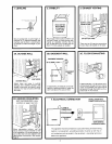
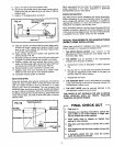
Figure#8 illustratesside exhaustventingpipeconnections 2. THE EXHAUST DUCT mustbe exhaustedtotheoutside
insidethe dryer cabinet. When ventingthe dryer from the usingmetalducting.Itshould notterminatebeneath the
side, the cabinet knockout must be removed.A 4" metal manufactured(mobile)home.
exhaust pipe must be purchased. The rear exhaust pipe
insidethe dryer must then be shortened. (Length willdepend 3. THE VENT HOOD must be securely fastened to the
on type of elbow purchased.) Secure the shortened pipe to manufactured (mobile) home structure.
the BlowerHousing with a screw atthe top, attach elbow and THIS DRYER IS NOT SUITABLE FOR USE IN RECRE-
metal exhaust pipe, and seal all jointswithtape or silicone
ATION VEHICLES SUCH AS TRAVEL TRAILERS,
bathtubcaulk. CAMPERS, OR MOTOR HOMES.
SIDE EXHAUSTING
LEFT SIDE i111 RIGHT SIDE
EXHAUSTING_._- ---_---. _"_........ /EXHAUSTING 1. Plugdryerin.
.;- 2. Following your operating instructions, operate the
- dryer briefly on all control settings, A slight odor
/ maybe noticed with a new machine.
ATTACHMENT SCREW HOLE
[_ 3. Allow empty dryer to operate on highest heat
/BLOWER HOUSING setting for a few minutes.
| 4, Stop dryer and wipe inside of cylinder with a clean
• '_ J
1.1
FRONT ACCESS cloth.
PANELJ 5. Wipe fingerprintsanddirt fromoutside ofdryerwith
I
soft cloth.
6. A protective plastic film may cover the control
panel,this shouldbe removed.