


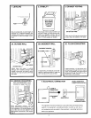
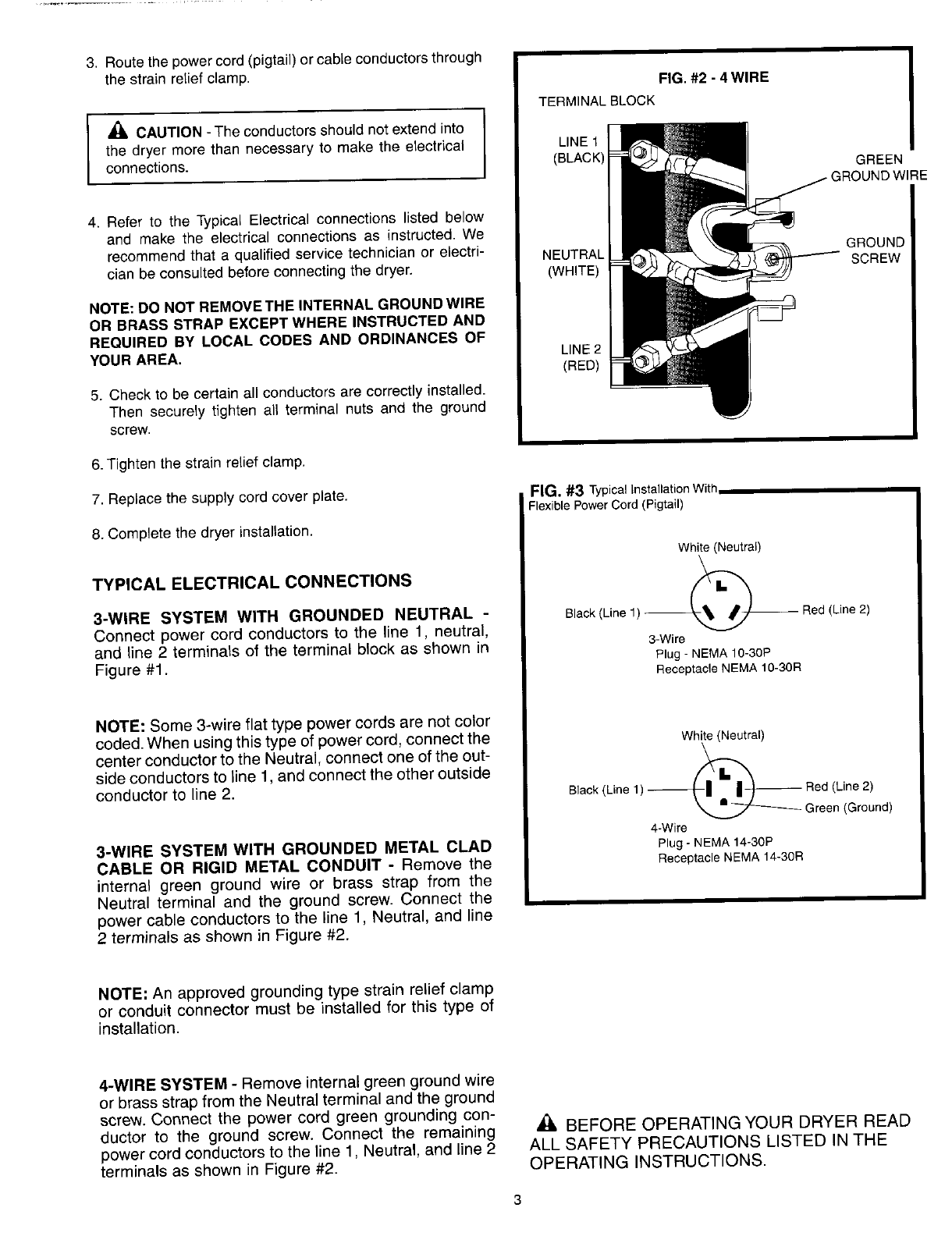
3. Route the power cord (pigtail) or cable conductors through
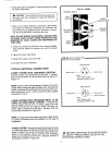
the strain relief clamp. FIG. #2 - 4 WIRE
TERMINALBLOCK
,_ CAUTION - The conductorsshould notextend into I
the dryermore than necessary to make the electrical J LINEt
connections. (BLACK) GREEN
_/IRE
4. Refer to the Typical Electricalconnections listed below
and make the electrical connections as instructed.We
recommendthat a qualifiedservice technicianor electri- NEUTRAL GROUND
clan be consultedbeforeconnectingthe dryer. (WHITE) SCREW
NOTE: DO NOT REMOVETHE INTERNAL GROUNDWlRE
OR BRASS STRAP EXCEPT WHERE INSTRUCTED AND
REQUIRED BY LOCAL CODES AND ORDINANCES OF
YOUR AREA. LINE2
(RED)
5. Check tobe certain all conductorsare correctly installed.
Then securely tighten all terminal nuts and the ground
screw.
6.Tighten the strain relief clamp.
7. Replace the supply cord cover plate. FIG. #3 TypicalInstallationWith
Flexible Power Cord (Pigtail)
8. Complete the dryer installation.
White (Neutral)
k
TYPICAL ELECTRICAL CONNECTIONS
3-WIRE SYSTEM WITH GROUNDED NEUTRAL - Black (Line 1) _ Red (Line 2)
Connect power cord conductors to the line 1, neutral,
and line 2 terminals of the terminal block as shown in 3-wire
Plug -NEMA 10-30P
Figure #1. ReceptacleNEMA10-30R
NOTE: Some 3-wire flat type power cords are not color
coded. When using this type of power cord, connect the White(Neutral)
center conductor to the Neutral, connect one of the out-
side conductors to line 1, and connect the other outside
conductor to line 2. Slack (Line 1) Red (Line 2)
Green (Ground)
4-Wire
3-WIRE SYSTEM WITH GROUNDED METAL CLAD Plug-NEMA14-30P
CABLE OR RIGID METAL CONDUIT - Remove the ReceptacleNEMA14-30R
internal green ground wire or brass strap from the
Neutral terminal and the ground screw. Connect the
power cable conductors to the line 1, Neutral, and line
2 terminals as shown in Figure #2.
NOTE; An approved grounding type strain relief clamp
or conduit connector must be installed for this type of
installation.
4-WIRE SYSTEM - Remove internal green ground wire
or brass strap from the Neutral terminal and the ground
screw. Connect the power cord green grounding con-
ductor to the ground screw. Connect the remaining _ BEFORE OPERATING YOUR DRYER READ
power cord conductors to the line 1, Neutral, and line 2 ALL SAFETY PRECAUTIONS LISTED IN THE
terminals as shown in Figure #2. OPERATING INSTRUCTIONS.
3