


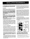

EXHAUSTVENTING RECUIREMENTS
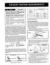
VENTHOODTYPE
WARNINI
FIRE HAZARD Numberof
90°Turns [_NEVER EXHAUST INTO A CHIMNEY, DUCT, GAS Separatedby --
VENT, WALL, CEILING, ATTIC, CONFINED SPACE, atleast4 ft.
BEDROOM, OR UNDER A BUILDING. ofStraightRun _]OPENING/n4" OPENING_JI_ 2_"
DO NOT USE VINYL, PLASTIC, CLOTH OR OTHER 0 45feet 30feet
NONMETALIC DUCT TO EXHAUSTTHE DRYER. 1 35feet 20feet
MULTIPLE INSTALLATIONS REQUIRE INDIVIDUAL 2 25feet 10feet
EXHAUST SYSTEMS.
Vent should never exceed 0.6 inches water column back
DRYERS INSTALLED IN A MANUFACTURED pressure, fluff empty dryer.
(MOBILE) HOME MUST BE VENTED OUTDOORS.
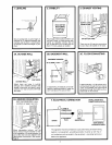
PERIODICALLY CLEAN LINT FROMVENT SYSTEM. BOTTOM EXHAUSTING
CLEAN FREQUENTLY IF USING MAXIMUM If space permits behind the dryer, a 4" elbowpointeddown-
LENGTH OF VENT. ward may be used to pass the exhaust system through the
floor. If this is not possible, the dryer may be exhausted
through the bottom as illustrated in FIG. #7. When exhaust-
Exhausting can be accomplished directly from the rear of ing in this manner, the installation should be made accord-
the cabinet, through right side of the cabinet, or down- ing to the following steps:
ward through the cabinet base. Ifyour existing ductwork is 1. Disconnect electric cord.
plastic, nonmetal, or combustible, replace it with METAL. 2. Raisethe top of the dryer by pressing in with a putty knife
Standard four inch diameter galvanized or aluminum pipe on the top panel retaining clips. FIG. #5.
should be used. DO NOT use any pipe which may be sus-
ceptible to rust or COMBUSTION. To avoid catching lint _p
the crimped end of each pipe section should face away FIG. #5 _ PROX 4"
from the dryer. Do not use screws or other fasteners that ,__.,__, _
extend into the exhaust pipe or duct.
Flexible 4" diameter metal tubing may be used for
exhausting the dryer. However, the convolutions create a
greater restriction than pipe and serious blockage can
result if the tubing is bent too sharply. If clearance to the
wall is less than 8 inches, use a 4" sheet metal elbow at
the rear of the dryer to avoid a sharp bend in the tubing. 3. Removefront panel by removing two'/4"screws inside top
Do not use over 8 feet (2.5 m.) of flexible metallic tubing corners of front panel. Disconnect door switch wires.
between the elbow and the vent hood. NOTE position of front seal before removing front panel.
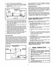
_---_ 4. Remove the cylinder as follows:
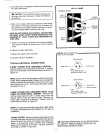
VENTHOOD ////Ill _ - -
The use of a vent hood _[ _ _ /-GROOVEDSIDE
ontheoutsideisrecom- _--mended. FIG'#6 _----_ "_'_ OFBELTDOwN
When the dryer stops the damper automatically closes to \_"_ ._S IDLERPULLEY
prevent drafts and the entrance of insects and rodents. To FRONTOF _,,,.-"_k\ _/I _ _ MOTOR
avoid restricting the outlet, maintain a minimum 8 inch DRYER P _'_._,/ PULLEY
clearance between the hood and the ground or other
obstruction. GROOVED SIDE /
OF BELT UP
FIG. #4 a. Forceidler pulley to the right and remove cylinder belt
PECONNECTION from idler and motor pulleys.See FIG. #6.
b. Lift up and turn cylinder to clear the roller supports.
---%
c. Lift out of cabinet.
EXHAUSTFLOW EXHAUSTFLOW 5. Remove tape and screw securing dryer vent pipe.
6. Removethe 4" dryer vent pipeand shorten to a suitable
I length. Lengthdepends on type of elbow purchased.
CORRECT INCORRECT 7. Remove knockout from dryer base.
LENGTHOFVENT 8. Place dryer in position and mark duct location on floor.
MaximumLengthof4" RigidDuct Checkfloor joistlocationbeforesawing holeinfloor.
5