


© 1998 Maytag Corporation
16008373-01 SECTION 8. MOTOR DRIVE SYSTEM
8-18-1
8-18-1
8-1
SECTION 8. MOTOR DRIVE SYSTEMSECTION 8. MOTOR DRIVE SYSTEM
SECTION 8. MOTOR DRIVE SYSTEMSECTION 8. MOTOR DRIVE SYSTEM
SECTION 8. MOTOR DRIVE SYSTEM
Warning Warning
Warning Warning
Warning
- Always shut off- Always shut off
- Always shut off- Always shut off
- Always shut off
electrical power to theelectrical power to the
electrical power to theelectrical power to the
electrical power to the
unit before beginning anyunit before beginning any
unit before beginning anyunit before beginning any
unit before beginning any
service procedures.service procedures.
service procedures.service procedures.
service procedures.
DRIVE BELTDRIVE BELT
DRIVE BELTDRIVE BELT
DRIVE BELT
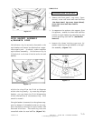
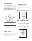
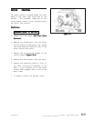
The drive belt has six (6) ribs which mate
with the face of the motor pulley. The belt
encircles the motor pulley and the drive
pulley of the spinner.
REMOVALREMOVAL
REMOVALREMOVAL
REMOVAL
1.
Disconnect power to the unit. Disconnect power to the unit.
Disconnect power to the unit. Disconnect power to the unit.
Disconnect power to the unit.
2. Roll the belt off the drive pulley and re-
move from the motor pulley.
ADJUSTMENTADJUSTMENT
ADJUSTMENTADJUSTMENT
ADJUSTMENT
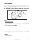
Check belt tension. If loose, remove the belt,
loosen the belt adjustment wheel bolt and
rotate the wheel one notch in a clockwise
rotation. Check belt tension again. The belt
should experience no more than 1" deflection
when depressed toward the inside
(Figure 8-1).(Figure 8-1).
(Figure 8-1).(Figure 8-1).
(Figure 8-1).
The motor drive system tear-down procedure
covers all components related to the drive
system, such as the drive motor, drive belt,
motor control, machine control and acceler-
ometer switch.
DRIVE MOTORDRIVE MOTOR
DRIVE MOTORDRIVE MOTOR
DRIVE MOTOR
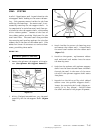
The drive motor is hinged into the left bottom
area of the outer tub and secured to the outer
tub by the bolt on the belt adjustment wheel.
A slot in the mounting bracket of the outer
tub allows the motor to pivot and allows
adjustment of the drive belt tension.
REMOVALREMOVAL
REMOVALREMOVAL
REMOVAL
1.
Disconnect power to the unit.Disconnect power to the unit.
Disconnect power to the unit.Disconnect power to the unit.
Disconnect power to the unit.
2. Remove the front panel, rear access panel
and the front weight
(See Front Panel &(See Front Panel &
(See Front Panel &(See Front Panel &
(See Front Panel &
Rear Access Removal).Rear Access Removal).
Rear Access Removal).Rear Access Removal).
Rear Access Removal).
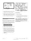
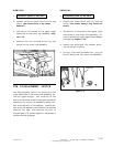
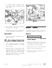
3. From the rear, locate the belt adjustment
wheel and note the adjustment number
aligned with the rib of the outer tub. This
will help later when the belt adjustment
wheel is placed back onto the outer tub
and the belt is remounted on the motor
and drive pulley. Remove the bolt secur-
ing the belt adjustment wheel
(Figure 8-2).(Figure 8-2).
(Figure 8-2).(Figure 8-2).
(Figure 8-2).
Figure 8-1Figure 8-1
Figure 8-1Figure 8-1
Figure 8-1