


© 1998 Maytag Corporation
16008373-01 SECTION 7. OUTER TUB & SPINNER ASSEMBLY
7-8
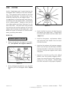
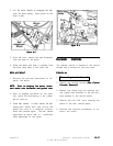
STRUT ASSEMBLY
Two struts are mounted to the base and in-
serted into rubber isolators in the rear of the
outer tub assembly. The struts provide sus-
pension support to the outer tub assembly.
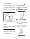
REMOVAL
1. Disconnect power to the unit.
2. Remove the front panel, top cover and
front shroud
(See Front Panel, Top Cover
and Front Shroud Removal).
3. Disconnect dispenser hoses and injector
hose connections to the outer tub.
4. Lean the cabinet forward to access the two
locking nuts that secure the struts to the
bottom of the base frame assembly. Use
an 8mm or ½" socket. Remove the lock-
ing nuts and lower strut washers.
5. With the washer standing upright, roll the
washer forward and off the struts, which
mount into the rubber isolators inserted
into the rear of the outer tub.
6. To Reinstall: Reverse the previous steps.
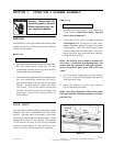
Isolator
Locking Nut
Lower Strut Washer
Rear Strut
Push Rod
Isolator
Strut
Figure 7-13
Strut Displacement Switch
1. Disconnect power to the unit.
2. Remove the rear access panel for imme-
diate access or remove the front panel.
3. Remove the wires to the switch.
4. Release the small locking tab on top of the
switch and rotate the switch to disengage
the switch from the strut.
5. To Reinstall: Reverse the aforementioned
steps.
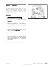
INERTIAL UNBALANCE SWITCH
The purpose of the switch is to monitor the
lateral horizontal movement of the outer tub
during spin (above 500 RPM), versus the ver-
tical movement. When a severe amount of
motion is detected, the machine control will
implement a reduction in speed or start a re-
distribution of the clothes load. This is done
by gradually stopping the motor. After the
motor stops, the tumbler will alternately
tumble, first in one direction then another. Af-
ter a brief time, the machine will again work
up to a full spin. Should the machine detect
another unbalance, the control will implement
another redistribution of the load.