


© 1998 Maytag Corporation
16008373-01 SECTION 6. WATER CARRYING COMPONENTS
6-1
SECTION 6. WATER-CARRYING COMPONENTS
Warning
- Always shut off
electrical power to the unit
before beginning any ser-
vice repair procedures.
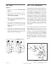
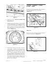
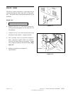
5. While pulling the bracket away from the
cabinet, rotate the left side of the bracket
away from the washer.
6. Remove the wire harness from the water
valve coils (Blue & White wires - Cold; Or-
ange & White wires - Hot) and remove the
clamp from the injector hose.
7. Remove two 5/16" hex head screws secur-
ing the valve to the mounting bracket.
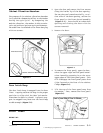
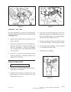
FRONT REMOVAL
1. Disconnect power to the unit.
2. Shut off the water supply to the inlet hoses.
3. Remove the front panel.
4. Remove dispenser bezel and raise the top
cover to expose the upper rear cabinet area
(See Front Panel & Top Cover Removal).
5. Remove the wire harness from the water
valve coils (blue & white wires - cold; or-
ange & white wires - hot) and remove the
clamp from the injector hose. When the
valve is replaced, the hot water valve coil
is on the left.
6. Remove the two 5/16" hex head screws se-
curing the water valve bracket to the
cabinet.
7. Carefully lift the valve and direct the inlet
hoses through the openings in the rear
mounting bracket.
8. Remove the inlet hoses from the water
valve connections. If possible, clamp the
hoses shut and/or have a towel handy in
case of overspray when water pressure is
relieved.
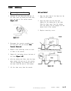
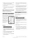
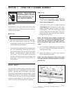
Mounting
Screws
Injector
Hose
Mounting
Bracket
Mounting Screws
Water
Valve
WATER VALVE
The water valve is accessible from the front
or rear of the machine.
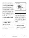
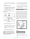
REAR REMOVAL
1. Disconnect power to the unit.
2. Shut off the water to the inlet hoses and
remove the hoses from the water valve
connections of the washer.
3. Remove the two ¼" hex head screws se-
curing the water valve bracket to the cabi-
net
(Figure 6-1).
4. While pulling the lower end of the bracket
down slightly, slide the bracket to the left.
This will allow the injector hose to clear
the rear cabinet opening.
Figure 6-1