


Section 4. Electrical Components & Testing
4-6
16010486 (16008373-05)
Revised 02/01
©2001 Maytag Appliances Sales Company
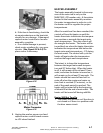
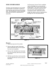
Motor Drive System Test
To check the system, check the board for
proper output to the motor control. This
is done by performing a board output
check. Then perform the Motor And
Motor Control Test.
Machine Control Board Output Test
1. Place the washer into Service Mode.
(See Section 2; Accessing Service
Mode)
2.
LED Washer: Access Board Output
Test and press Stain Cycle. This will
send a signal to the motor control to
operate the motor. This will test the
board relay for 120 VAC output to the
motor control board. Motor will not
operate, because the door is not
locked.
LCD Washer: Access Service Tests
and press system check. Touch the
screen to toggle the motor control on.
This will test the board relay for 120
VAC output to the motor control
board.
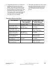
Motor Phases
With the introduction of the sensorless
motor, the Motor Phase Test is no longer
required. If the motor experiences a
phase problem, the motor will not run.
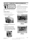
Motor & Motor Control Test
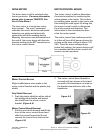
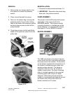
1. Disconnect power to the washer.
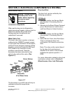
2. Remove the front panel and pull the
JP4 Connector from the motor control
board. (Figure 4-6)
3. Reconnect the washer power cord to
supply voltage.
4. Press Help and Back function to acti-
vate Service Mode.
5.
LED Washer: Select Board Output
Test; close door or push door
acturator button; touch the stain cycle
membrane switch.
LCD Washer: Select System Check;
close door or push door actuator
button: touch Toggle Motor Control
On
6. The motor control will immediately
execute a test routine and the motor
should run, rotating the spinner at 50
rpm.
7. If the motor runs, and the spinner
rotates at the proper RPM speed: the
problem lies outside of the motor and
motor control circuit. Disconnect
power to the washer and reconnect
the JP4 Interface connector to the
motor control.
If the motor runs, and the spinner
does not rotate: Check for missing
belt.
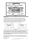
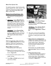
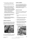
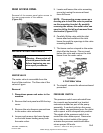
8. If the motor does not run:
a. Check the 10 amp fuse located on
the control board, either visually or
with an ohm meter. If bad, replace
motor control/wire harness assembly
completely. (Figure 4-7)
Figure 4-6