


14 John Deere Operator's Manual
WATER SUPPLY:
1. Select a water supply hose which is a quality grade of garden hose measuring
at least 3/4" ID and no longer than 50 feet.
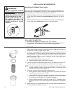
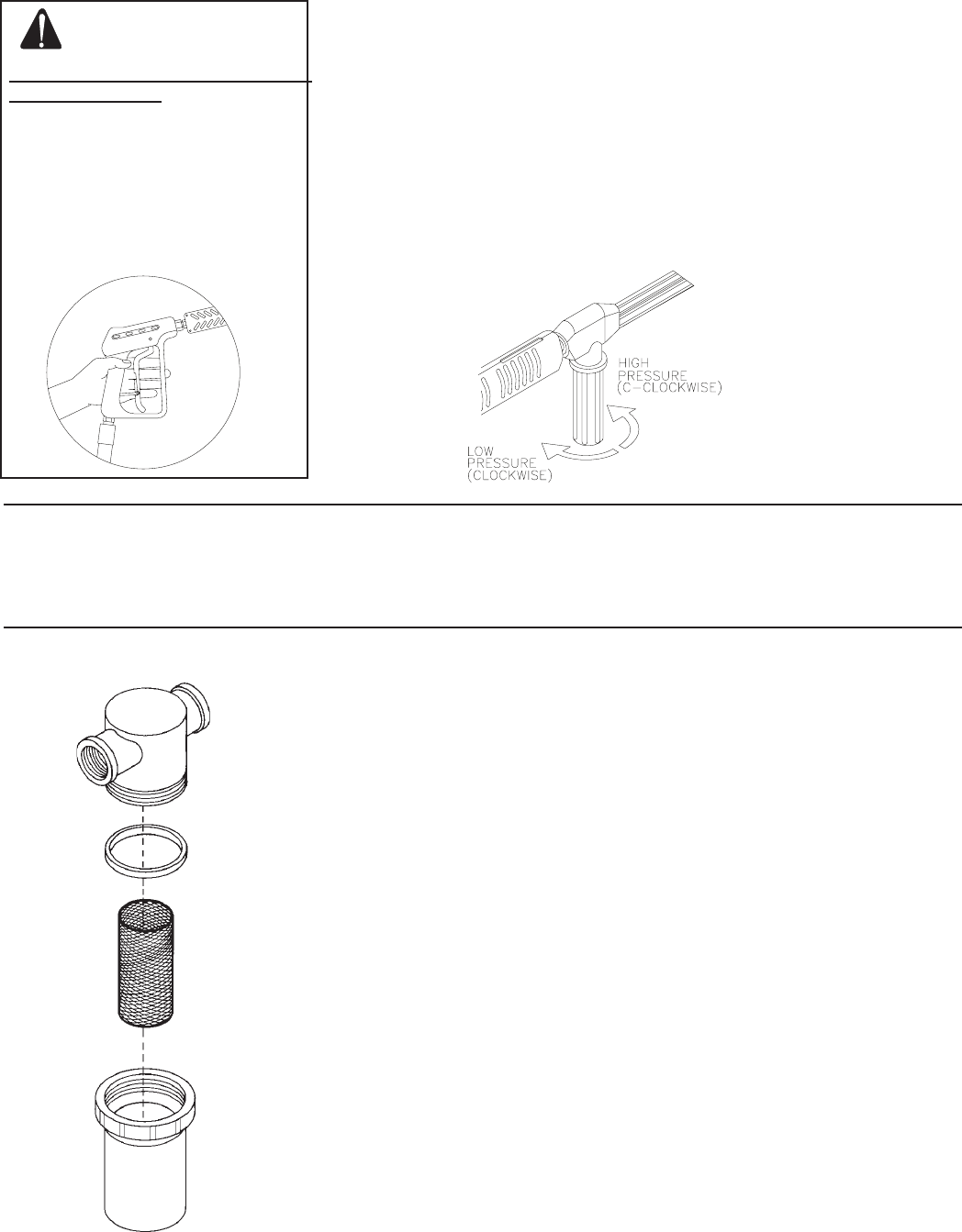
2. If your unit is equipped with a water strainer, ensure it is clean and free of
any obstructions. Periodic cleaning of the water strainer will help prevent
pump problems. As a strainer becomes obstructed, it restricts proper flow of
water to the pump. This can result in cavitation which will cause premature
failure of pump packings.
a. Unscrew the strainer bowl from the unit.
b. Remove strainer screen and clean or replace.
3. Connect one end of the water supply hose to the water inlet of the unit.
Connect the other end of the hose to your pressurized water supply.
NOTE: If there is a high mineral content in your water, it is recommended that
a water softener be used to prevent the possibility of excessive scale
buildup inside the heat exchanger coil.
4. Follow the incoming water requirements listed below:
a. Water pressure must be between a minimum of 20 pounds per square
inch (PSI) and a maximum of 125 PSI.
b. Incoming GPM must be approximately one gallon more than the outgoing
GPM stated on the pressure washer nameplate. (You can check GPM
by timing how long it takes to fill a 5 gallon container.)
c. Incoming water temperature must not exceed 125°F. Excessive pump
damage may result if the water temperature exceeds this acceptable
level.
5. Never allow the unit to operate without the incoming water line attached and
the water supply completely turned on.
INSTALLATION & PREPARATION
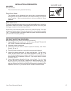
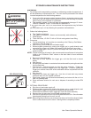
ADJUSTABLE PRESSURE DUAL LANCE:
This unit features an Adjustable Pressure Dual Lance which allows the user
to select a high or low pressure "fan" spray. Simply rotate the adjustable grip
on the dual lance to achieve the desired pressure selection.
1. Selection of high pressure can be achieved by turning the adjustable grip
on the Dual Lance assembly counterclockwise as shown in the figure
below.
2. Selection of low pressure can be achieved by turning the adjustable grip
on the Dual Lance clockwise as shown in the figure below.
DUAL LANCE CONNECTION:
1. Be certain the trigger gun is locked in the "OFF" position.
2. Connect the dual lance assembly to the trigger gun assembly at this time
(if applicable). Be certain the connection is securely tightened.
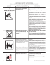
WARNING
RISK OF INJECTION CAUSING
SEVERE INJURY!
-THE TRIGGER GUN SHOULD
ALWAYS BE LOCKED IN THE OFF
POSITION WHEN NOT IN USE!
-NEVER LOOK DIRECTLY AT
THE NOZZLE UNLESS IT IS
DISCONNECTED FROM THE
TRIGGER GUN/DUAL LANCE
ASSEMBLY!