


© Copyright, Alliance Laundry Systems LLC – DO NOT COPY or TRANSMIT
Washer-Extractors
5-08-51
55
Installation
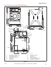
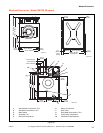
Models IWF014, IWF018, IWF025 and
IWF030 (M-speed)
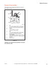
Surface
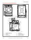
The machine must be securely fixed on a flat surface
(metal base, concrete or solid ground). The anchoring
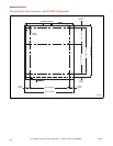
is to be done on the 6 provided places in the holes on
the corners of the base. (See Mounting Bolt Hole
Locations). Refer to Figure 32.
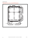
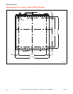
Figure 32
The machine must be placed entirely level. For easy
maintenance it is recommended to keep a minimal
distance of 23.62 in. (600 mm) between the wall and
the back of the machine.
If several machines are placed next to each other, there
should be a minimal distance of 1.18 in. (30 mm)
between each machine.
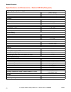
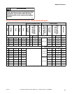
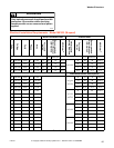
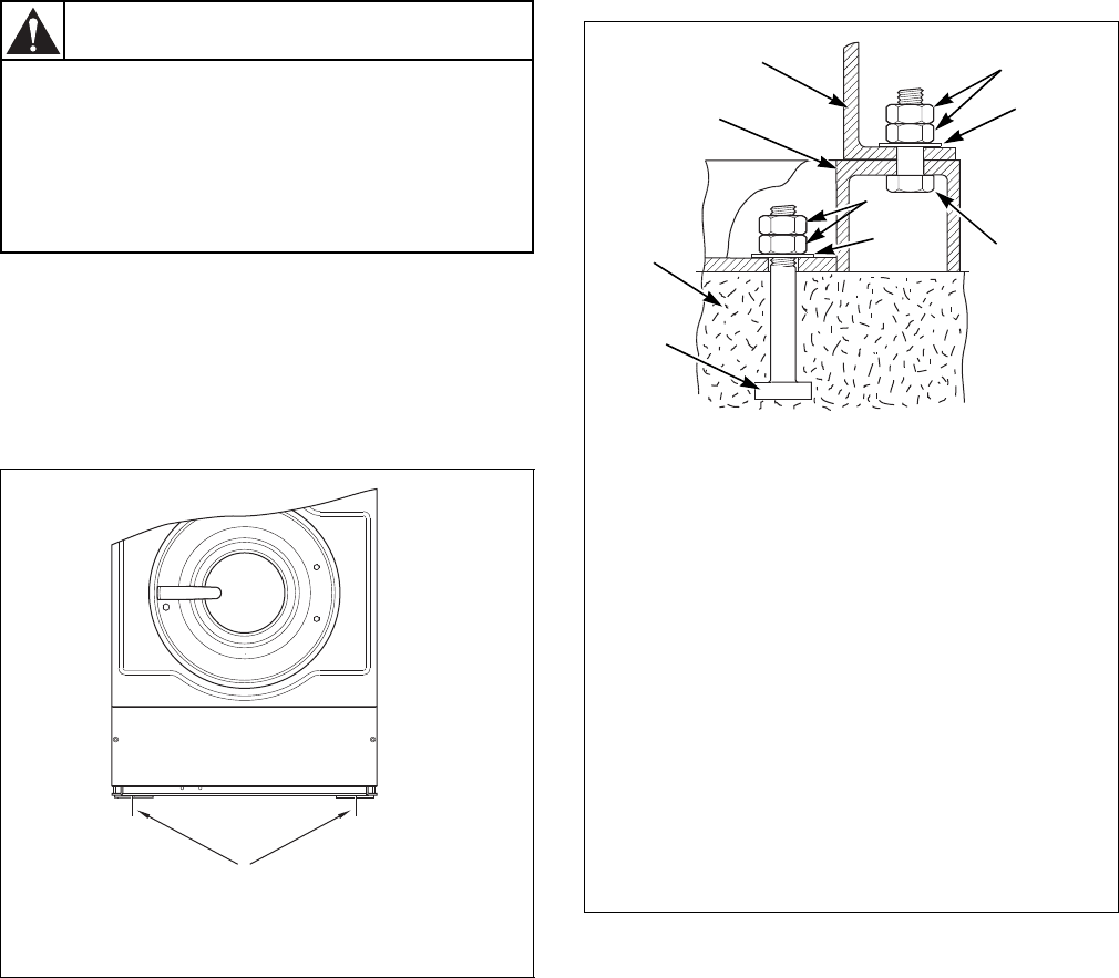
Anchoring to Metal Base
The machines must be fixed on a metal base which is
securely anchored on a concrete base. Refer to
Figure 33.
Figure 33
CHM2102N
1 Mounting Bolt Holes
Ensure that the machine is installed on a
level floor of sufficient strength and that
the recommended clearances for
inspection and maintenance are provided.
Never allow the inspection and
maintenance space to be blocked.
SW020
CAUTION
CHM2102N
1
CHM2103N
1 Machine Base
2 Nut
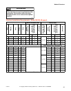
.5 in. (M12) (Models IWF014, IWF018 and
IWF025), .625 in. (M16) (Model IWF030)
3 Washer
1.57 in. x 0.60 in. x 0.15 in.
(40 mm x 17 mm x 4 mm)
4 Bolt
.625 in. x 2.5 in. (M16x60 mm)
5 Bolt
.5 in. (M12) (Models IWF014, IWF018 and
IWF025), and .625 in. (M16) (Model IWF030)
6 Concrete Base
9.48 in. (250 mm) (Models IWF014, IWF018
and IWF025), and 13.77 in. (350 mm)
(Model IWF030)
7 Metal Base
CHM2103N
1
2
3
7
4
6
2
3
5