


Installation instructions
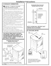
Minimum Clearance Other Than Alcove or Closet Installation
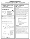
Minimum clearance m combustible surfhces and for air opening are: 0 in. clearance bofl_ sides and 1 in. rear. Consideration
must be given m provide adequate clearance for proper operation and service.
FT]PREPARING FOR iNSTALLATiON
OF NEW DRYER
TIP: Install your dryer before installing your washer,
This will allow better access when installing dryer exhaust,
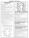
DiSCONNECTiNG GAS
TURNGAS
SHUT-OFFVALVE Id_
TOTHEOFF LL_._:q:v
DISCONNECTANDDISCARDOLD_/__
FLEXIBLEGASCONNECTORAND
OLDTRANSITIONDUCTING
MATERIAL.REPLACEWITHNEW
CSA(AGA)APPROVEDFLEXIBLE
GASLINECONNECTORANDUL
APPROVEDTRANSITIONDUCT.
a'k
_WARNING - NEVER REUSE OLD
FLEXIBLE CONNECTORS.
The use of okt flexible connectors can cause leaks and
personal ii_iury. Always use new flexible connectors when
installing gas appliances.
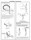
REMOVING LiNT FROM WALL
EXHAUST OPENING
* Remove and discard existing plastic or metal foil
transition duct and replace with UL listed transition
duct.
WALL
/
INTERNALDUCT CHECKTHATEXHAUST
OPENING HOODDAMPEROPENS
ANDCLOSESFREELY.
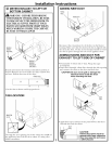
TILTTHEDRYERSIDEWAYS
ANDREMOVETHEFOAM
SHIPPINGPADSBY
PULLINGATTHESIDES
ANDBREAKINGTHEM
AWAYFROMTHEDRYER
LEGS.BESURETO
REMOVEALLOFTHE
FOAMPIECESAROUND
THELEGS.
_q GAS REQUIREMENTS
WARNING
* Installation IIIUSE conf()l'IIl tO local codes and ordinances,
or in their absence, the NATIONAL FUEL (;AS CODE,
ANSI Z223.
* This gas dryer is equipped with a Valve & Burner Assem-
bly for use only with natural gas. Using conversion kit
WE2 5X0217, your local smwice organization can convert
this dwer for use with propane (LP) gas. ALL CONWER-
SIONS MUST BE MADE BY PROPERLY TRAINED
AND QUALIFIED PERSONNEL AND IN ACCOR-
DANCE WITH LOCAL CODES AND ORDINANCE
REQUIREMENTS.
* The dxyer must be disconnected flom the gas supply
piping system during any pressure testing of that system
at a test pressure in excess of 0.5 PSI (3.4 KPa).
* The dryer must be isolated flom the gas supply piping
system by closing the equipment shut-offvalve during
any pressure testing of the gas supply piping of test
pressme equal to or less than 0.5 PSI (3.4 KPa).
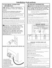
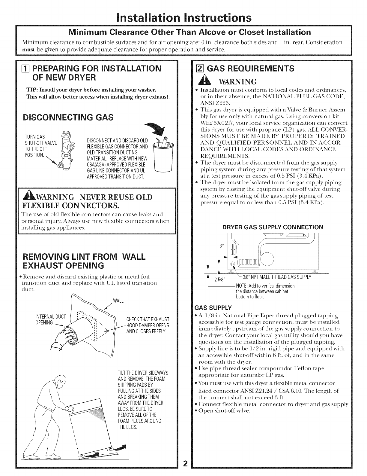
DRYER GAS SUPPLY CONNECTION
l 2-5/8"
" 3/8"NPTMALETHREADGASSUPPLY
NOTE:Addtoverticaldimension
thedistancebetweencabinet
bottomtofloor.
GAS SUPPLY
* A 1/8-in. National Pipe Taper thread plugged rapping,
accessible for test gauge connection, must be installed
immediately upstream of the gas supply connection to
the dryer. Contact your local gas utility should you have
questions on the installation of the plugged tapping.
* Supply line is to be 1/2-in. rigid pipe and equipped with
an accessible shut-off within 6 fL oL and in the same
room with the dwer.
* Use pipe thread sealer compoundor Teflon rope
appropriate for naturabr LP gas.
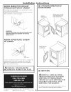
* You must use with this dryer a flexible metal connector
listed connector ANSI Z21.24 / CSA 6.10. The length of
the connect shall not exceed 3 fL
* Connect flexible metal connector to dryer and gas supply.
* Open shut-off valve.
2