


40 electrolux building-in
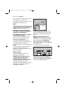
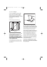
With the appliance installed adjust all
four feet ensuring the machine is stable,
and a clearance of approximately 5 mm
is left between the top of the machine
and the underside of the worktop.
A final check for stability should be car-
ried out with the machine on spin with a
load, this will identify the need for any
further fine adjustment to the feet.
A strip of beading approximately 605
mm W, x 5 mm H, x 25 mm D must be
screwed down into the base directly in
front of the machine’s feet, this will pro-
vide additional security.
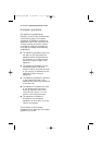
If required an additional door magnet,
part number 1242394-00/3 and disc,
part number 1242393-00/5 are available
from spare parts.
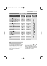
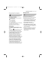
600-605
5 X 25 X 605
Hardwood strip
5 mm x 25 mm
H
490
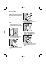
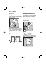
If it is not possible to use one solid
piece, due to the additional height
required, ensure that any additional
strips of timber are glued and screwed
to the underside of the base
(see Fig.F).
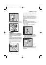
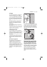
Drill four fixing holes see Fig. G
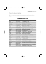
Position the base into the recess with
its front edge as far forward as the
adjoining plinth line will allow.
The reason for placing the base in
this position is to allow a small
strip of beading to be fitted in front
of the appliance feet.
Fix the base firmly to the floor using
four appropriate countersunk screws
(see Fig. H).
600-605 mm
50 mm
Front edge
Top view
95 mm
490 mm
G
132969690_GB.qxd 13/09/2007 11.38 Pagina 40