


NA
7
www.aristonappliances.us
Installation
Water Connection
Caution
1. The washing machine must only be operated
with cold and hot (max. 140°F//60°C) tap water.
Do not connect the appliance to the mixer tap of an
unpressured hot-water boiler.
2. To prevent water damage, the hot and cold water
valves should be accessible when the washer is in
place and should always be turned off when the
washer is not in use.
! Remember: please use the new hoses supplied,
fitted to the machine. Old hoses may cause leaks due
to worn out washers or may be split due to water
pressure.
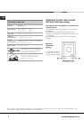
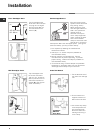
Connecting the water inlet hoses
Included in the accessories supplied with the machine
are 2 inlet hoses. The straight end of these hoses should
be connected to the supply.
The 90° angled end of these hoses should be connected
to the inlet valves on the back of the machine to make a
water tight seal on each connection (see below figure).
The couplings should be tightened by hand, a tool should
only be used if a leak occurs. Do not use excessive
force.
Repair or replacement of a part should be made only by
a qualified service technician to prevent personal injury or
damage to the machine. Inlet valves are color coded:
Red = Hot / White = Cold
Connection.
1. Screw the cold water
fill hose (C blue connector)
onto the cold water supply
until tight.
2. Turn on the cold water
supply and check for
leaks, tighten if necessary.
3. Screw the hot water fill
hose (H red connector)
onto the hot water supply until tight.
4. Turn on the hot water supply and check for leaks,
tighten if necessary.
Drainage Connection
Standpipe Diameter/Capacity. Needs a 1 1/4 minimum
diameter standpipe with a minimum carry-away capacity of
7 gallons per minute.
Top of Standpipe. Must be between 25 - 34 inches (62-
86 cm) high measured from the bottom of the machine.
Outlet End of Drain Hose (provided with the unit).
Must be at least 20 above the bottom of the washer. An
air break must be available at the standpipe to avoid
siphoning. No more than 6 of the drain hose should be
inserted into the drain pipe to prevent siphoning.
! Although you may need to move the hooked end support
along the grey drainage hose,, DO NOT remove it.
! Whichever draining method you use, make sure that the
hooked end support is fixed level to, or above the
Plumbing Indicator Line.
You should carefully position the drain hose to avoid
kinks and ensure proper drainage of the water.
The outlet end of the drain hose must be at least 25 (62
cm) above the base machine. At this point it s possible
for the water to be discharged into a sink or drain pipe, but
an air break must be available at this 24 height to prevent
the machine from syphoning (see figures page 8).
No more than 6 of the drain hose should be inserted
in the drain pipe.
Important.
Make sure that the drain hose is not kinked and the
water flow has not been restricted.
The machine must rest solid on a sturdy floor for
optimum performance and minimum vibration.
Hints and tips
! Make sure there are no kinks or bends in the
hose.
! The water pressure at the supply tap must be
within the values indicated in the Technical
details table (see table on page 4).
Always use a new inlet hose.
Check the water inlet hose at least once a year,
replace if cracked as worn hoses could split under
water pressure.
Do not overtighten. The couplings should be
tightened by hand; a tool should only be used if a
leak occurs. Do not use excessive force.
H
C