


31
I. COMPRESSED AIR
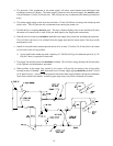
This dryer is manufactured with a pneumatic Air Jet damper system, which requires an external supply of
compressed air of 0.75 CFH. The air connection is made at the rear of the top console.
1. Air Requirements
2. Air Connection
Air connection to system --- 1/8 F.P.T.
3. No air regulator or filtration is provided with the dryer. External regulation/filtration of 80 PSI (5.51 bars)
must be provided. It is suggested that a regulator/filter gauge arrangement be added to the compressed air
line just before the dryer connection. This is necessary to insure that correct and clean air pressure is
achieved.
J. PREPARATION FOR OPERATION/START-UP
The following items should be checked before attempting to operate the dryer:
1. Read ALL CAUTION, WARNING, and DIRECTION labels attached to the dryer.
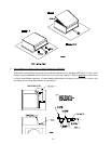
2. Check incoming supply voltage to be sure that it is the same as indicated on the dryer data label that is
affixed to the left side panel area behind the top control (access) door (refer to the illustration on page 9).
In the case of 208 VAC or 240 VAC, THE SUPPLY VOLTAGE MUST MATCH THE ELECTRIC
SERVICE EXACTLY.
3. GAS MODELS - check to assure that the dryer is connected to the type of heat/gas indicated on the dryer
data label.
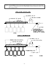
4. GAS MODELS - the sail switch damper assembly was installed and pre-adjusted at the factory prior to
shipping. However, each sail switch adjustment must be checked to assure that this important safety
control is functioning.
5. GAS MODELS - be sure that ALL gas shutoff valves are in the open position.
6. Be sure that ALL electric box covers have been replaced.
7. Check ALL service doors to assure that they are closed and secured in place.
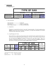
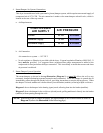
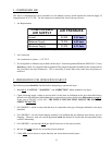
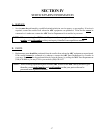
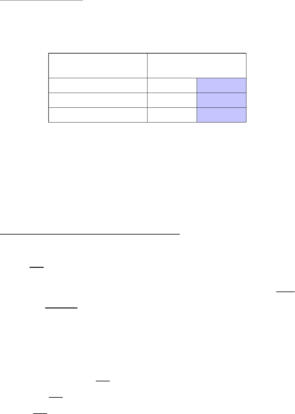
COMPRESSED
AIR SUPPLY
AIR PRESSURE
Normal 80 PSI 5.51 bars
Minimum Supply 70 PSI
4.82 bars
Maximum Supply 90 PSI
6.21 bars
Shaded areas are stated in metric equivalents