


© Copyright, Alliance Laundry Systems LLC – DO NOT COPY or TRANSMIT
Installation
F232102
36
Supply Compartments
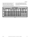
Supply compartments on 135 pound and 250 pound
capacity models are located on the left side of the
washer-extractor. To access supply cups, release the
rubber door latch by pulling it down until it clears the
door latch bracket. Using the plastic door handle on
the right side of the supply door, lift the door up and
back until it rests in a fully open position. The supply
cups can be removed and filled as desired. Supply
compartments are numbered 1 – 5 from the rear of the
washer-extractor.
Connecting External Liquid Supplies to
the Washer-Extractor
135 Pound Capacity Models
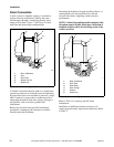
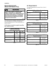
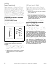
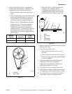
Hose barbs are located on the right rear of the washer-
extractor. Connections are numbered as shown in
Figure 21.
Figure 21
To connect external supplies, use the following
procedure:
1. Connect tubes to supply inlets by pushing each
tube over inlet lip. Tubes should fit snugly onto
supply inlets. When seated completely, tube ends
should contact rear of washer-extractor.
2. Tightness of fit will dictate whether or not hose
clamps are necessary. No. 8 hose clamps are
suitable.
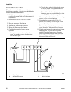
250 Pound Capacity Models
External supply connections for the 250 pound
capacity washer-extractor are located on top of the
supply dispenser. Hose connections should be made
via the strain relief.
1. Remove plugs from base. Plugs are assembled
inside the tubing ring.
2. Install strain reliefs, included in the seal nut.
3. Insert tubes through base. Do not remove cups.
Tube should extend into the plastic cup, with the
exception of the softener tube, which should be
routed to the outside of the cup.
4. Tighten the seal nut to prevent tubing from
escaping the assembly.
Electrical Connections for Chemical
Injection Supply Systems
135 Pound Capacity Models
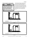
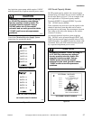
On 135 pound capacity models, the external supply
terminal strip is located in the rear control module, on
the left side. Refer to Figure 22 for examples of decals
applicable to 135 pound capacity models.
Terminals SUPPLY 1 through SUPPLY 5 provide
100 – 120VAC fused at 500mA. These terminals may
be used to provide signals to the chemical injection
system but must not be used to provide power to the
pump. Do not attempt to increase fuse rating as this
may cause damage to the washer-extractor’s circuitry.
An external chemical injection system requiring
200 – 240VAC can be powered through LINE 1 and
LINE 2 on the external supply terminal strip on PVQ
and PVT models. Any chemical injection system used
with PVM, PVN, and PVP models must be powered
by a separate independent power source.
R071I
1
2
3
4
5
1
2
3
6
7
8
4
5
R07
1
5 SUPPLY MODELS
8 SUPPLY MODELS