


© Copyright, Alliance Laundry Systems LLC – DO NOT COPY or TRANSMIT
Installation
F232102
26
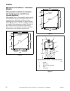
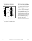
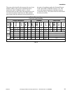
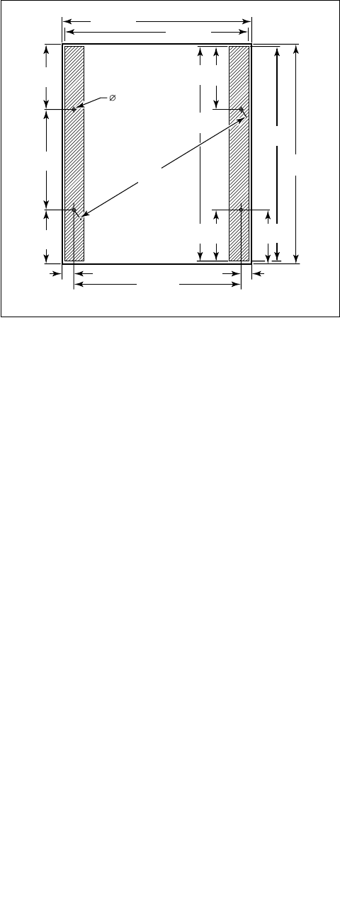
6. Fill the spaces between the tilt base and floor
with a good quality non-shrinking machinery
grout to ensure a stable installation. Refer to
Figure 15.
Figure 15
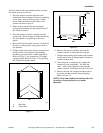
7. Remove the spacers carefully, allowing the tilt
mechanism to settle into the wet grout.
8. Position the mounting bolt washers and locknuts
on the anchor bolts and fingertighten locknuts to
the tilt base.
9. After the grout is completely dry, tighten the
locknuts by even increments – one after the
other – until all are tightened evenly and the tilt
mechanism is fastened securely to the floor.
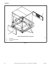
10. Using the appropriate equipment, lift the washer-
extractor and place on top of the tilt mechanism
aligning the same four holes from which the
threaded rods were removed.
Four 1-1/4 x 6 inch GR-8 Hex Head screws (Part
No. 430478) are shipped in a plastic bag inside
the basket of the washer-extractor. Position one
of the washers (previously removed from the
threaded rod) under the head of one of the screws
and place the screw in one of the holes. Position
another washer on the screw and attach a nut
(retained from the removal of the threaded rods).
Repeat for all four holes. Then fasten tightly to
secure the washer-extractor to the tilt mechanism.
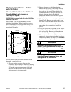
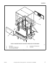
11. Remove the front and lower rear panels on the
washer-extractor. Then remove the four red
transport brackets used to secure the machine
during shipping. Refer to Figure 16.
12. Reinstall all previously removed panels prior to
start-up of the washer-extractor.
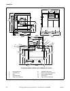
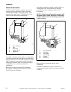
CFS218N
66 in.
(1676 mm)
5 in.
(127 mm)
5 in.
(127 mm)
24 in.
(610 mm)
40.69 in.
(1034 mm)
26.31 in.
(668 mm)
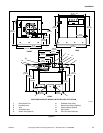
77.5 in.
(1969 mm)
1.25 in.TYP
(32 mm)
76 in.
(1930 mm)
89 in.
(2261 mm)
74 in.
(1880 mm)
91 in.
(2311 mm)
89 in.
(2261 mm)
23 in.
(584 mm)
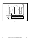
24 in.
(610 mm)
25.31 in.
(643 mm)