


© Copyright, Alliance Laundry Systems LLC – DO NOT COPY or TRANSMIT
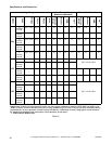
Specifications and Dimensions
F8138601
46
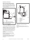
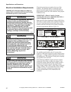
Electrical Installation Requirements
IMPORTANT: Electrical ratings are subject to
change. Refer to serial decal for electrical ratings
information specific to your machine.
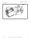
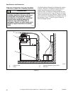
Electrical connections are made at the rear of the
machine. The machine must be connected to the
proper electrical supply shown on the identification
plate attached to the rear of the machine, using copper
conductors only.
IMPORTANT: Alliance Laundry Systems
warranty does not cover components that fail as a
result of improper input voltage.
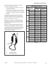
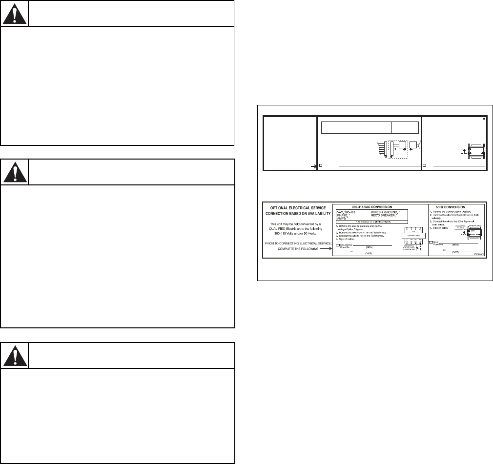
Make sure the correct transformer jumper (208 Volt or
240 Volt) is in place. Refer to the “optional” Electrical
Service Connection label located on the back of the
machine near the electrical service input for machine
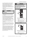
electrical requirements. Refer to Figure 24.
Figure 24
On variable-speed models, the AC inverter drive
requires a clean power supply free from voltage spikes
and surges. A voltage monitor should be used to check
incoming power. The customer’s local power company
may provide such a monitor.
The following conditions require corrective action,
contact the local utility to adjust the voltage. If the
local utility cannot adjust the input voltage, install a
buckboost transformer to lower the input voltage.
Input voltage is above 240V or 480V, phase to ground
voltage exceeds 125% of normal line to line voltage,
or 240V open delta configuration (stinger leg).
Contact the distributor or the manufacturer for
assistance.
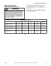
This machine must be installed, adjusted,
and serviced by qualified electrical
maintenance personnel familiar with the
construction and operation of this type of
machinery. They must also be familiar
with the potential hazards involved.
Failure to observe this warning may result
in personal injury and/or equipment
damage, and may void the warranty.
SW004
WARNING
Dangerous voltages are present in the
electrical control box(es) and at the motor
terminals. Only qualified personnel
familiar with electrical test procedures,
test equipment, and safety precautions
should attempt adjustments and
troubleshooting. Disconnect power from
the machine and wait 3 minutes before
removing the control box cover, and
before attempting any service
procedures.
W702
WARNING
Ensure that a ground wire from a proven
earth ground is connected to the ground
lug near the input power block on this
machine. Without proper grounding,
personal injury from electric shock could
occur and machine malfunctions may be
evident.
SW008
WARNING
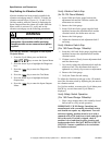
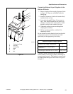
VAC: 200-208
PHASE: *
AMPS: *
* As indicated on
original serial plate
200-208 VAC CONVERSION
50Hz
Operation
50Hz CONVERSION
1. Refer to the Control Transformer area on
the Control Option Diagram.
2. Remove the "240V" Transformer Jumper in
the control box.
3. Replace with "208V" Transformer Jumper
found in the diagram pack.
4. Sign off below.
1. Refer to the Control Option Diagram.
2. Remove the wire from the 60Hz tap on drain
valve(s).
3. Connect the wire to the 50Hz Tap on all
drain valves.
4. Sign off below.
(SIGN)
(SIGN)
(DATE)
(DATE)
on
on
F8099701R1
200-208VAC
Operation
Transformer Jumper
208V
This unit may be field converted
by a QUALIFIED Electrician to
the following 200-208 Volts
and/or 50 Hertz.
PRIOR TO CONNECTING
ELECTRICAL SERVICE,
COMPLETE THE FOLLOWING
OPTIONAL ELECTRICAL SERVICE
CONNECTION BASED ON
AVAILABILITY
WIRES & GROUND: *
REC'D BREAKER: *
Drain Valve(s)
50Hz
60Hz N
Connection
for 50Hz
Operation Only
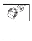
PHM740N
PHM756N
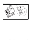
PHM740N
PHM756N
O, Q, X AND Y – VOLTAGE MODELS
N, P AND R – VOLTAGE MODELS