


© Copyright, Alliance Laundry Systems LLC – DO NOT COPY or TRANSMIT
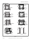
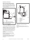
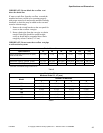
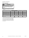
Specifications and Dimensions
F8138601
38
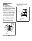
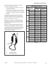
Gap Setting for Vibration Switch
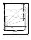
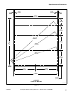
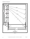
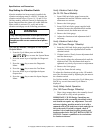
After the machine has been properly installed, the
vibration switch gap must be verified. To locate the
vibration switch refer to Figures 18, 19 and 20. For
UniLinc models, while the control is displaying the
Inputs Outputs Menu the alarm will sound when the
frame switch is activated. To verify and set the
vibration switch gap use the following procedures:
For UniLinc Models, Navigate to the Inputs
Outputs Menu:
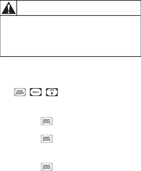
1. From the Cycle Menu press and hold the
, , keys to enter the System Menu.
2. Press the arrow keys to highlight the Diagnostic
box.
3. Press the key to enter the Diagnostic
Menu.
4. Press the key to enter the Test Menu.
5. Press the arrow keys to highlight the Inputs
Outputs box.
6. Press the key to enter the Inputs Outputs
Menu.
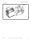
Verify Vibration Switch Gap
(for 35-125 Pound Models):
1. Insert 0.009 inch feeler gauge between the
adjustment bolt and the vibration switch; the
alarm must not activate.
2. Remove the feeler gauge
3. Insert 0.010 inch feeler gauge (supplied with
machine) between the adjustment bolt and the
vibration switch; the alarm must activate.
4. Remove the feeler gauge.
5. Adjust the vibration switch adjustment bolt if
necessary.
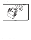
Verify Vibration Switch Gap
(For 150 Pound Design 1 Models):
1. Insert the 0.010 inch feeler gauge (supplied with
machine) between the adjustment bolt and the
vibration switch.
2. If alarm is active: Slowly loosen adjustment bolt
until the alarm stops.
3. Very slowly tighten the adjustment bolt until the
alarm activates. The adjustment bolt must be
tightened very slowly to prevent over adjustment.
4. Remove the feeler gauge.
5. Verify the Frame Switch setting.
To adjust the vibration switch gap on the 150 models,
move the vibration switch by adjusting the jam nuts on
the vibration switch.
For UniLinc models, to return to the Cycle Menu press
BACK key several times until Cycle Menu is
displayed.
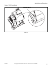
Verify Safety Switch Operation
(For 150 Pound Design 2 Models):
1. Place a large magnet above the normally-closed
ball switch to verify switch operation.
IMPORTANT: UW150 Design 2 machines are
manufactured with a normally-closed ball switch
and should not require any adjustment. To avoid
nuisance tripping, machine must be level with a
summed value of 3/8 inch front to back and right to
left to the earth. If switch is tripped, check if
machine is level and then for pour grouting and
broken anchor bolts. DO NOT BYPASS SAFETY
SWITCH. Contact a qualified service technician
for further assistance.
Only trained personnel should perform this
procedure. Use caution while servicing
machines with covers removed and power
applied.
W700
WARNING