


Installation/Operation Supplement
F232148 (EN)
10
© Copyright, Alliance Laundry Systems LLC – DO NOT COPY or TRANSMIT
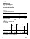
Dimensional Clearances
NOTE: The dimensions shown here are for
planning purposes only. They are approximate and
subject to normal manufacturing tolerances. If
exact dimensions are required for construction
purposes, contact the distributor or manufacturer.
We reserve the right to make changes at any time
without notice.
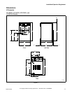
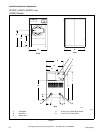
V-Computer
SF18VNV, SF25VNV, UF18VNV, and
UF25VNV Models
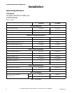
Both single and multiple machine installations require
specified minimum clearances on all sides of each
machine. Tables below show these clearances.
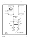
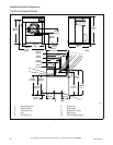
WE-6 Computer
SF35-85PV, UF35-85PV, SF135-250PV, and
UF135-250PV Models
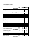
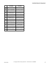
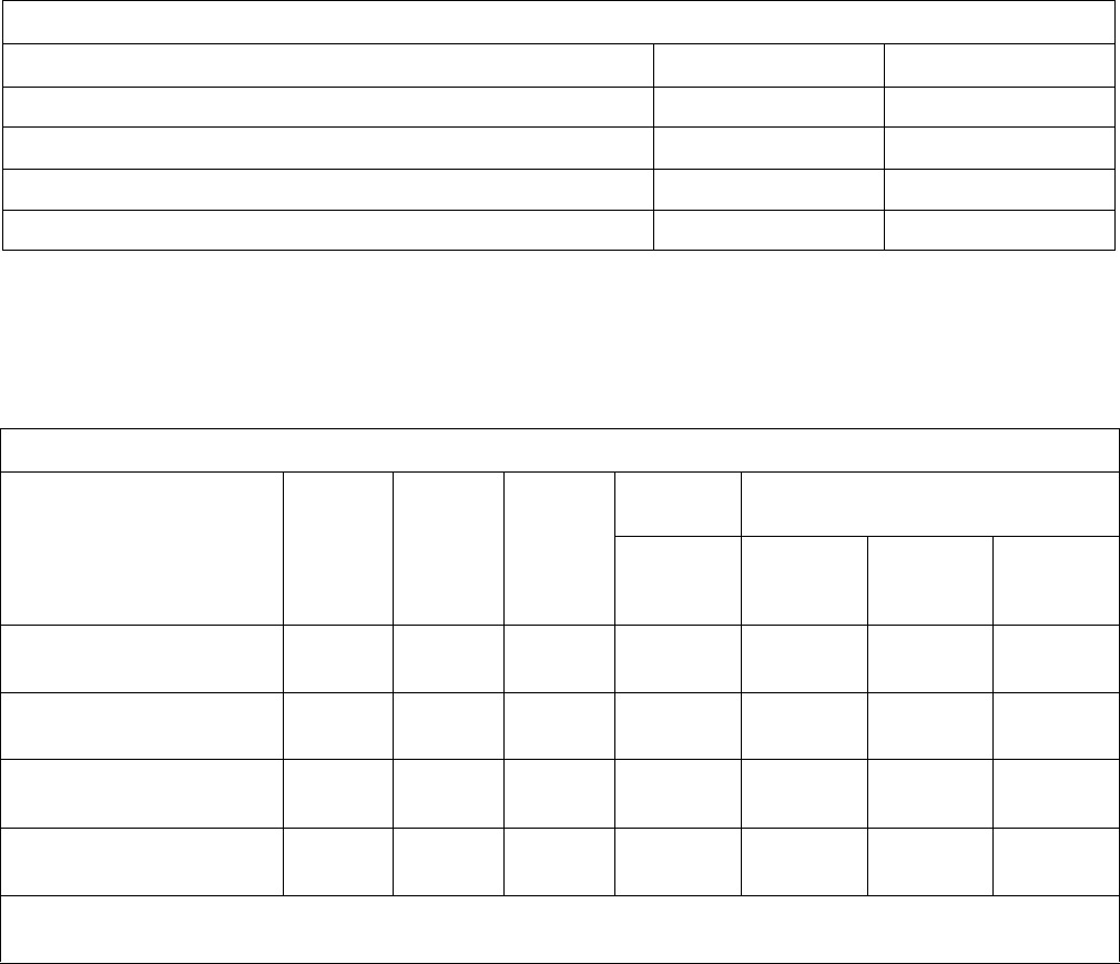
Recommended Minimum Clearances
18 Pound 25 Pound
Minimum rear clearance, mm (in.) 305 (12) 305 (12)
Minimum clearance between machine and wall, mm (in.) 50 (2) 50 (2)
Minimum clearance between machines (side), mm (in.) 25 (1) 25 (1)
Minimum front clearance, mm (in.) 406 (16) 445 (17.5)
Table 4
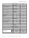
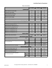
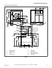
Recommended Minimum Clearances
35
Pound
50
Pound
85
Pound
135
Pound
250 Pound
Standard Standard
Forward
Tilt
Option*
Two-Way
Tilt
Option*
Minimum rear clearance,
mm (in.)
450 (18) 450 (18) 450 (18) 610 (24) 610 (24) 914 (36) 914 (36)
Minimum clearance between
machine and wall, mm (in.)
150 (6) 150 (6) 150 (6) 457 (18) 457 (18) 457 (18) 457 (18)
Minimum clearance between
machines (side), mm (in.)
25.4 (1) 25.4 (1) 25.4 (1) 457 (18) 457 (18) 457 (18) 457 (18)
Minimum front clearance,
mm (in.)
533 (21) 584 (23) 584 (23) 584 (23) 914 (36) 914 (36) 914 (36)
* Machines equipped with the tilt option require a minimum overhead clearance as well. Refer to
Figure 7 for the minimum
overhead clearance for the 250 pound capacity model with tilt option.
Table 5