ELECTRIC FRYERS - SERVICE PROCEDURES AND ADJUSTMENTS
12
MELT TEMPERATURE
CALIBRATION (SOLID
STATE CONTROL)
WARNING:
DISCONNECT THE ELECTRICAL
POWER TO THE MACHINE AT THE MAIN
CIRCUIT BOX. THERE MAY BE TWO SEPARATE
CIRCUITS. BE SURE BOTH ARE
DISCONNECTED. PLACE A TAG ON THE
CIRCUIT BOX INDICATING THE CIRCUIT IS
BEING SERVICED.
1. Place a thermometer in the center of the vat at
one inch below the shortening surface.
2. Allow the shortening to cool below 135 F.
3. Remove the screws securing the control panel
and allow it to swing downward.
4. Disconnect the electric harness and remove the
control panel.
5. Remove the melt temperature adjustment
screw sealant by gently chipping away with a
screwdriver. (screw located to the right of pin
#12)
6. Turn the adjustment screw clockwise to the
stop position.
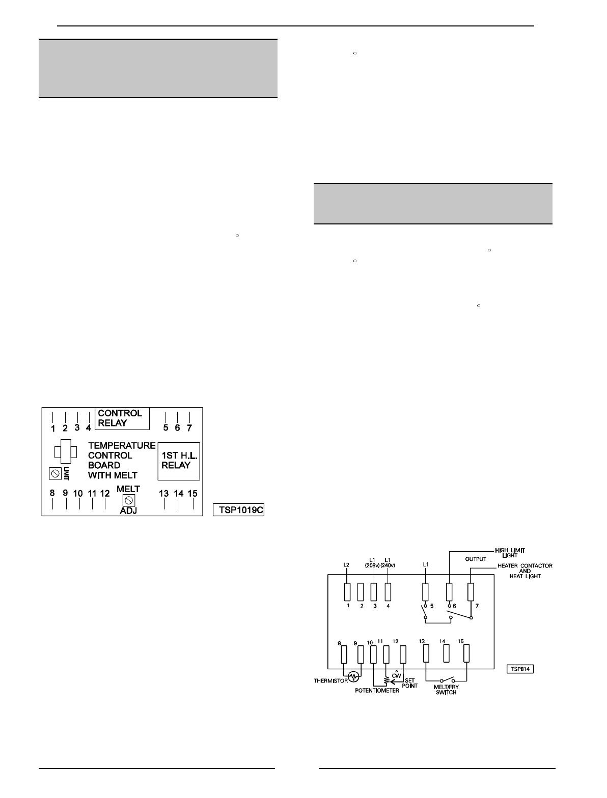
7. Connect a DC voltmeter between pins 13 and
15 on the electronic control board.
8. Reconnect the control panel wiring harness.
9. Reconnect the power supply.
10. While holding the control panel in your hand,
turn the power switch on.
11. Set the temperature control to the frying
temperature and the melt switch to melt.
12. The voltmeter should read 5 VDC.
13. When the shortening temperature reaches
135 F, turn the adjustment screw
counterclockwise until the voltmeter reads 0
VDC.
14. Place a small drop of enamel paint or fingernail
polish in the center of the screw.
15. Disconnect the power and remove the
voltmeter.
16. Install the control panel.
CONTROL BOARD TEST
(SOLID STATE CONTROL)
1. Check the temperature of the shortening. The
temperature should be below 300 F and above
135 F.
2. Access the control board.
3. With the potentiometer set at 0 , turn the
power switch on and check the incoming
voltage.
A. 120 volts, between pins 1 - 2 and I - 5.
B. 208 or 240 Volts, between pins 1 - 3 and 1
- 5
C. 240 Volts, between pins 1 - 4 and 1 - 5
(Export only)
4. Check the potentiometer as outlined under
“TEMPERATURE CONTROL TEST”.
5. Check the thermistor temperature probe as
outlined under “THERMISTOR PROBE
RESISTANCE CHART”.
6. Set the control to call for heat, the heat light
should light.
7. Check for output voltage between pins 1 - 7.
8. Replace the control board if there isn't any
output.


