5
5. Features
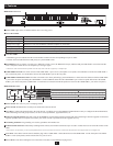
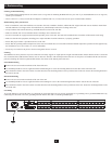
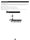
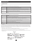
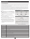
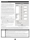
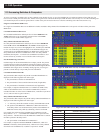
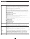
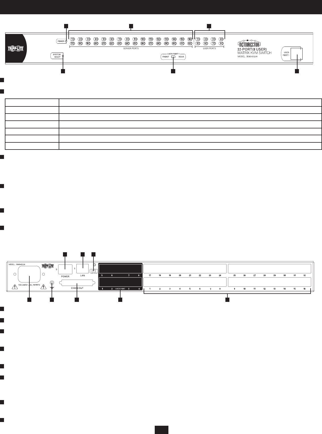
B060-032-8 Front View
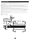
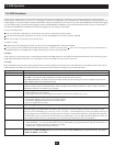
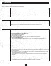
B060-032-8 Rear View
Power LED: Lights (blue) to indicate that the unit is receiving power.
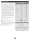
Server Port LEDs:
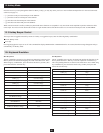
Port LED Status
Steady Amber Light KVM Port is selected and the connected computer is powered on
Flashing Amber Light KVM Port is selected and is cascaded to a powered on KVM Switch
Steady Green Light KVM Port is not selected and the connected computer is powered on
Flashing Green Light KVM Port is not selected and is cascaded to a powered on KVM Switch
Steady Red Light KVM Port is selected and the connected computer is powered off
No Light KVM Port is not selected and the connected computer is powered off; or there is no computer connected to the KVM Port
User Port LEDs:
• Illuminates (green) to indicate that the console module connected to the corresponding user port is online.
• Flashes when cascaded from the KVM port(s) of a parent KVM switch.
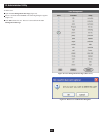
Reset Button: Press to perform a system reset.* When the system is reset, the B060-032-8 beeps, and the KVM port LEDs fl ash in succession until the
reset is completed. After the reset is completed you can log in again.
* This button is semi-recessed and must be pushed with a thin object such as the end of a paper clip or a ballpoint pen.
USER PORT 1 Switch: This switch selects which USER PORT 1 port is active (front panel or rear panel). Set to FRONT to activate the USER PORT 1
port on the front panel; set it to REAR to activate the USER PORT 1 port on the rear panel.
USER PORT 1 Maintenance Port: Provides convenient access when performing system maintenance. It shares the same function with the USER PORT
1 port on the rear panel. Switching the USER PORT 1 switch to FRONT deactivates the USER PORT 1 port on the rear panel and activates the USER
PORT 1 port on the front panel. (USER PORT 1 switch must be returned to the REAR position to reactivate the USER PORT 1 port on the rear panel.)
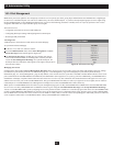
Power Socket: The unit’s AC power cord plugs in here.
Power Switch: Standard rocker switch powers the KVM switch on and off.
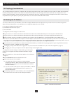
LAN Port: Connects the KVM Switch to the local network, providing access to the B060-032-8 Administrator Utility to confi gure the KVM installation,
create and manage user and group accounts, set device access permissions, upgrade fi rmware, etc.
Firmware Upgrade Switch: Place this switch in the NORMAL position during normal operation and while performing a fi rmware upgrade. If a fi rmware
upgrade operation does not complete successfully, this switch is used to perform a fi rmware upgrade recovery.
Grounding Terminal: The grounding wire used to ground the unit attaches here.
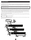
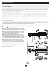
DAISY-CHAIN OUT Port: When daisy-chaining KVM switches, the DAISY-CHAIN OUT port is used to connect the lower-level KVM switches in the
chain.
* If this feature is not operational, your unit requires updated fi rmware. Contact your dealer for assistance or check for the latest fi rmware in the Support Section at www.tripplite.com.
User Ports: Cat5 cables from the console modules plug in here. USER PORT 1 shares KVM access with USER PORT 1 on the front panel. The USER
PORT 1 switch (front panel) controls which of the two ports is active.
Server Ports: Cat5 cables linking the Server Interface Units (SIUs) to the B060-032-8 plug in here.
1
1
2 3 4
1 5 6 7 8
1 2 3
2
2
3
3
4
4
4 5 6
5
5
6
6
7
8