E6581301
J-1
10
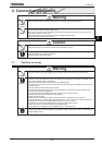
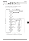
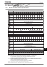
10. Selection of peripheral devices
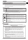
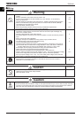
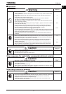
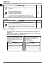
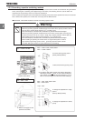
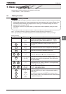
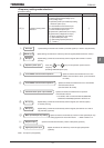
Warning
Mandatory
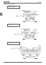
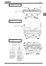
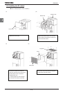
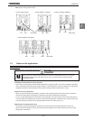
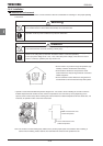
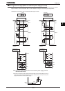
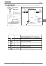
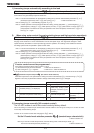
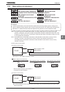
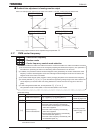
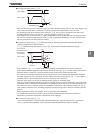
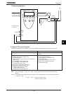
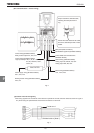
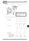
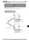
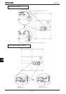
• When using the inverter without the front cover, be sure to place the inverter unit inside a cabinet. If
they are used outside the cabinet, it may cause electric shock.
Be Grounded
• Be sure to ground every unit. If not, it may cause electric shock or fire on the occasion of failure,
short-circuit or electric leak.
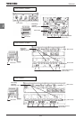
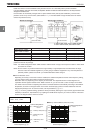
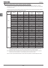
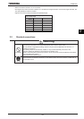
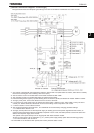
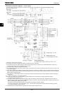
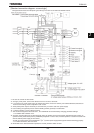
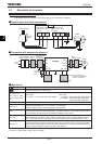
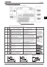
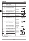
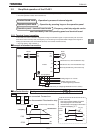
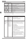
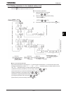
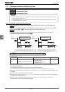
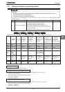
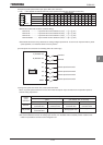
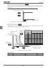
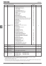
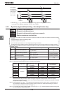
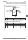
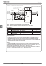
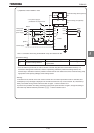
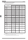
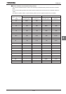
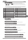
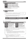
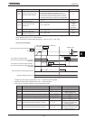
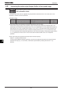
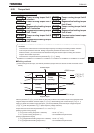
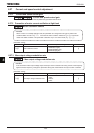
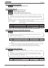
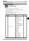
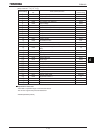
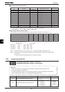
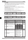
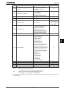
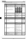
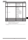
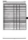
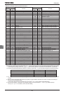
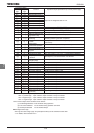
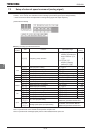
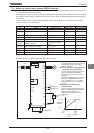
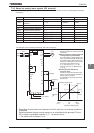
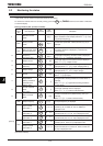
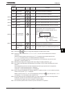
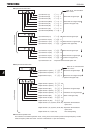
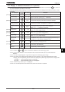
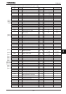
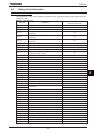
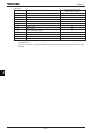
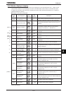
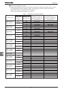
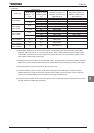
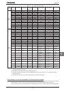
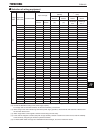
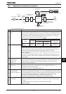
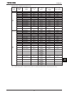
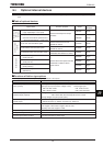
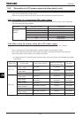
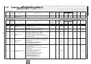
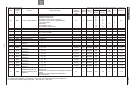
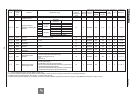
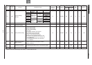
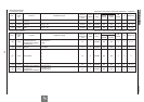
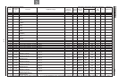
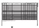
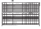
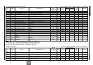
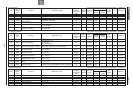
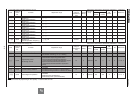
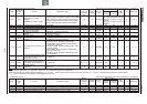
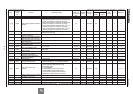
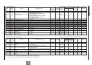
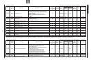
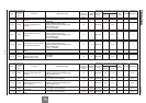
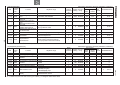
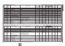
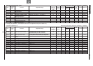
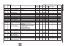
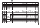
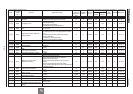
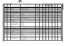
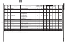
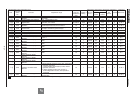
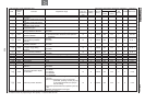
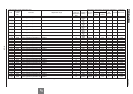
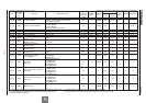
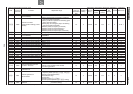
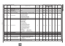
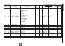
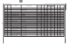
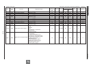
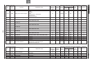
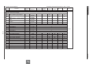
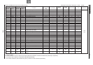
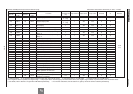
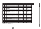
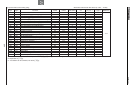
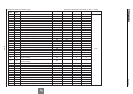
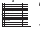
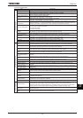
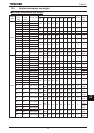
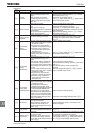
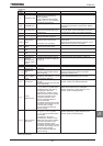
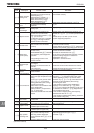
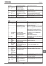
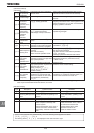
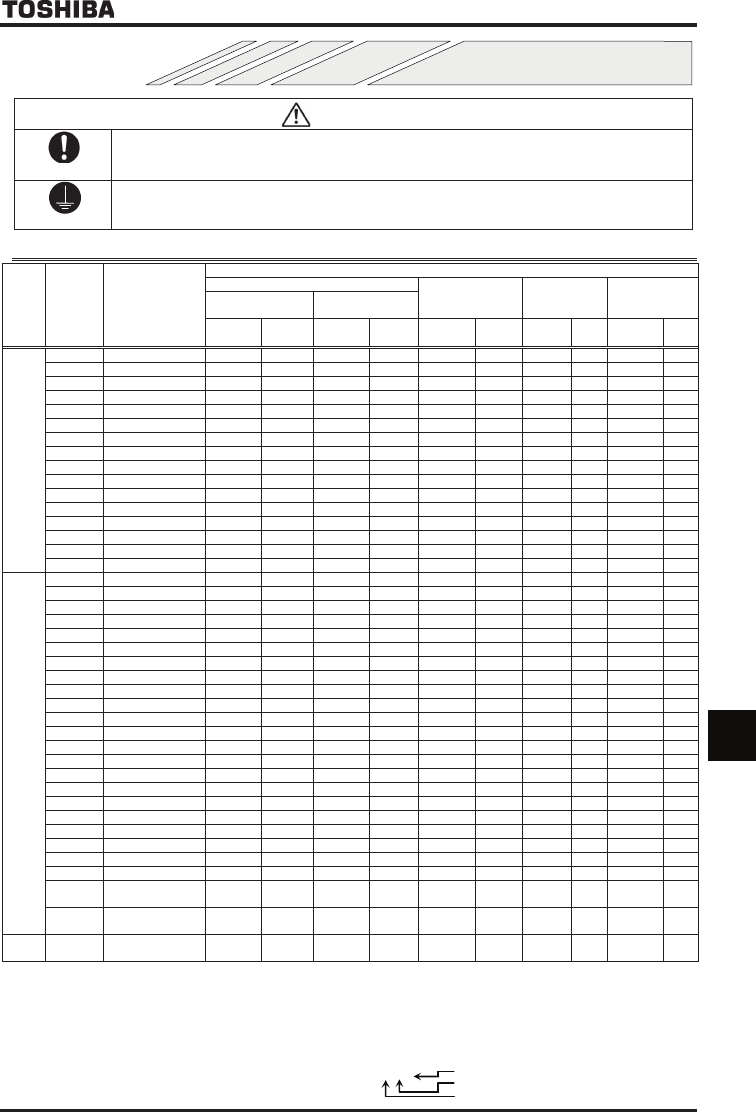
10.1 Selection of wiring materials and devices
Voltage
class
Applicable
motor
[kW]
Inverter model
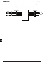
DC terminal
Braking resistor/
Braking unit
(optional) (*4)
Earth cable
AWG
(*5)
mm
(*6)
AWG
(*5)
mm
(*6)
AWG
(*5)
mm
(*6)
AWG
(*5)
mm
(*6)
AWG
(*5)
mm
(*7)
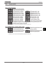
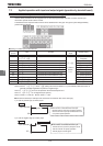
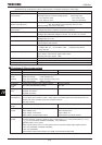
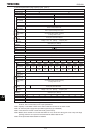
200V
class
400V
class
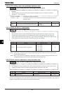
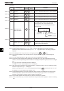
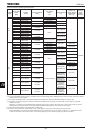
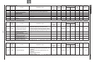
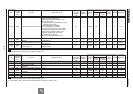
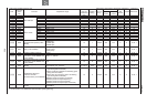
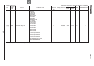
355
VFAS1-4355KPC
×2×2 (*9,10)
150
×3
500MCM×3
185
×4
350MCM×2
185
×2 4/0
120
×2
400
VFAS1-4400KPC
×2×2 (*9,10)
185
×3
500MCM×4
350MCM×2
185
×2 4/0
150
×2
500
VFAS1-4500KPC
×3×2 (*9,10
500MCM×4
350MCM×2
185
×2 250MCM
150
×2
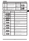
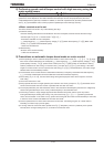
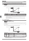
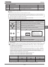
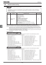
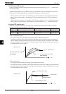
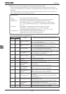
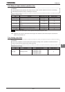
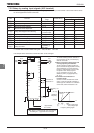
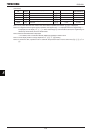
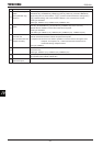
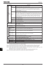
(*1): The recommended cable size is that of the cable (e.g. 600V class, HIV cable) with continuous maximum permissible temperature of 75°C. Ambient
temperature is 40°C or less and the wiring distance is 30m or less.
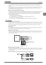
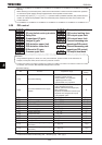
(*2): For the control circuit, use shielded wires whose size (cross-section) is 0.75 mm
2
or more.
(*3): For the earth cable, use wires larger than the specified ones in size (cross-section).
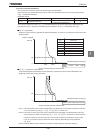
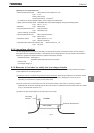
(*4): Recommended wire size for an optional braking resistor. Refer to 5.19 for use of external braking resistor.
(*5): This cable size is conformity to UL508C.
(*6): This cable size is conformity to IEC60364-5-52.
(*7): This cable size is conformity to IEC60364-5-54.
(*8): The recommended cable is 600V class HIV cable with permissible temperature of 90°C.
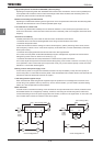
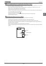
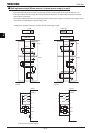
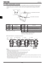
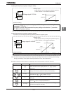
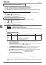
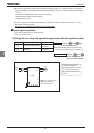
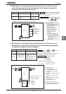
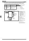
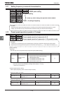
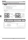
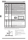
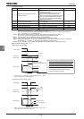
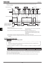
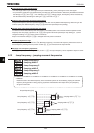
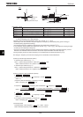
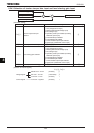
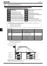
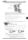
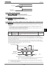
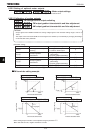
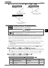
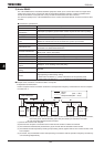
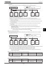
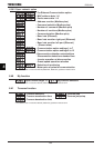
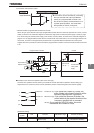
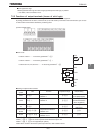
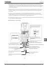
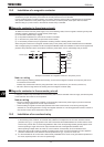
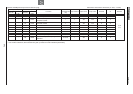
(*9):
The number refers to a cable composition. For example, in the case of “120×2×2”: 120×2×2
Number of cables connected in parallel on the terminal board
Number of cables connected to each terminal board
Wire size 120mm
2