22
Locations marked “Reserved” in Table 1 are reserved for future use. Although
any data placed in these locations is currently ignored, future firmware
releases may use these locations for data transfer.
Two other modules are also available (Module 3 and Module 4). These
modules are primarily intended for applications that require a compact data
size, and do not need access to all available drive parameters.
Module #3, intended for applications where only one drive is connected to the
PBDP-110 (via Channel A), is comprised of four bytes structured as two 16-bit
words. Module #4, intended for applications where drives are connected to
both Channel A and Channel B, is comprised of eight bytes structured as four
16-bit words. Both of these modules are combined in Table 2.
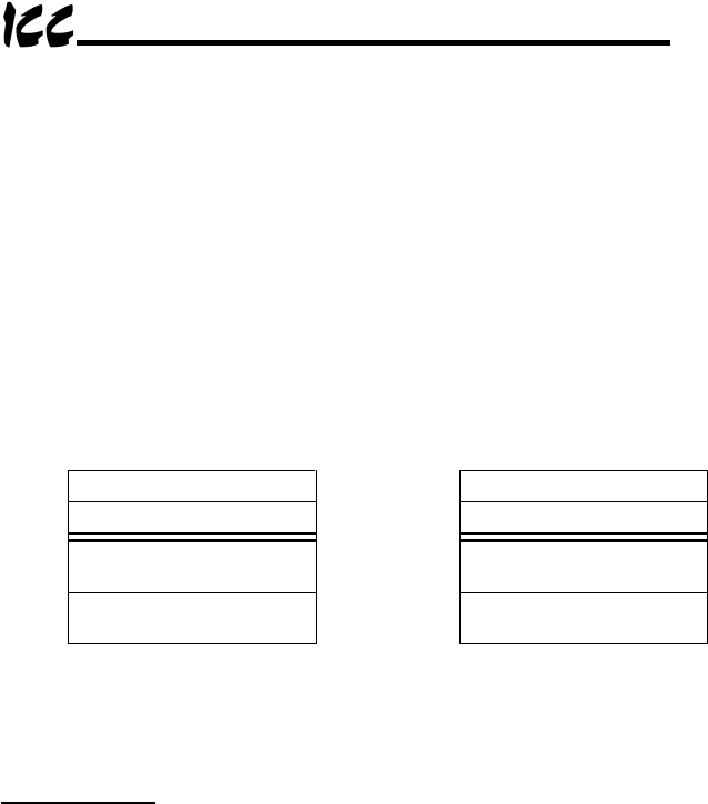
Table 2: Module 3 and Module 4 Output Data Format
Offset Data Offset Data
0 Drive A command high byte 4 Drive B command high byte
1 Drive A command low byte 5 Drive B command low byte
2
Drive A frequency
command high byte
6
Drive B frequency
command high byte
3
Drive A frequency
command low byte
7
Drive B frequency
command low byte
The format of all information transferred for Drive B is identical to that for Drive
A. Therefore, all data descriptions given here apply equally for both Drives A
and B.
Command Word
Bit-mapped drive control command word (drive parameter number FA00). This
is the location where run/stop, etc. commands are written. An example
command word can be found in Table 3. Because the format of this command
word depends on the drive’s specifications, please refer to your specific drive’s
Serial Communications Manual for the exact structure of this word.
Using the example command word in Table 3, some representative command
words that can be used to control your drive via the Profibus network are:
0xC400.......Profibus command valid, Profibus frequency valid, run forward
0xC600.......Profibus command valid, Profibus frequency valid, run reverse
0xC000.......Profibus command valid, Profibus frequency valid, stop
0xE000.......Profibus command valid, Profibus frequency valid, reset fault
Although the above examples all show Profibus command and frequency valid,
input (status) data can always be monitored from the network regardless of the
settings of bits 14 and 15 in the command word.
