2-12
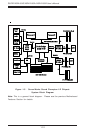
SUPER X5DL8-GG/X5DLR-8G2+/X5DLR-8G2 User’s Manual
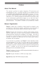
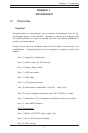
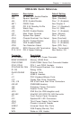
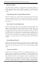
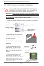
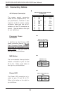
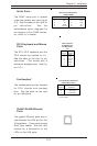
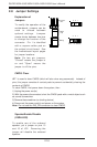
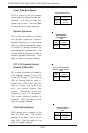
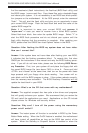
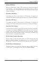
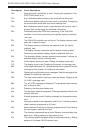
HD LED Indicator (JF2)
The HD LED connector located at
JF2 is used to indicate activity on
any hard drive (IDE, SCSI or CD-
ROM).
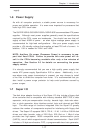
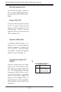
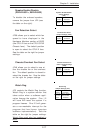
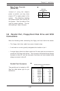
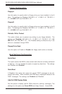
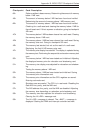
Speaker (X5DL8-GG)
A speaker header/jumper is lo-
cated on JF2. You may enable the
onboard speaker by jumping pins
13 & 15 of JF2. To use an exter-
nal speaker, connect the speaker
header to pins 9 through 15.
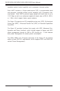
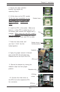
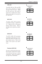
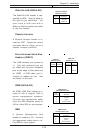
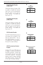
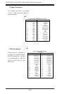
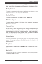
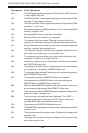
Power LED (JF2)
The Power LED connection located
at JF2 is used to inform you that
power is being supplied to the
motherboard. There is also an
onboard LED for this function (see
CR5 in Section 2-6).
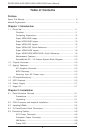
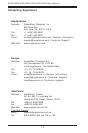
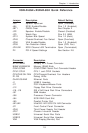
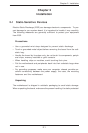
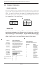
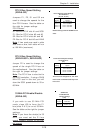
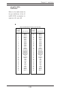
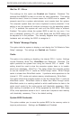
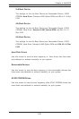
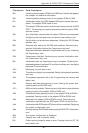
Third Power Supply Fail
Header
Connect a cable from your power
supply to the JP46 header to pro-
vide warning of power supply fail-
ure. The warning signal is passed
through the PWR_LED pin on JF1
to provide indication of a power
failure on the chassis. Note: This
feature is only available when us-
ing Supermicro power supplies.
See the table on the right for pin
definitions.
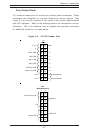
Third Power Supply Fail Header
Pin Definitions (JP46)
Pin
Number
1
2
3
4
Definition
P/S 1 Fail Signal
P/S 2 Fail Signal
P/S 3 Fail Signal
Reset (from MB)