Chapter 1: Introduction
1-9
Introduction
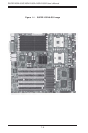
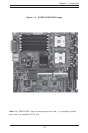
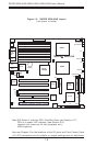
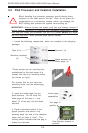
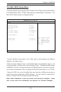
X5DLR-8G2+/X5DLR-8G2 Quick Reference
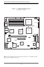
Jumper Description Default Setting
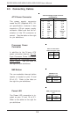
J35 Spread Spectrum Open (Disabled)
JA4 SCSI Enable/Disable Pins 1-2 (Enabled)
JBT1 CMOS Clear See Chapter 2
JP2 Speaker Enable/Disable Closed (Enabled)
JP3 Watch Dog Pins 2-3 (NMI)
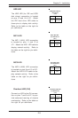
JP12 System Bus Speed Pins 1-2 (Auto)
JP48 Chassis/Overheat Fan Select Open (Overheat)
JP56 VGA Enable/Disable Pins 1-2 (Enabled)
JP58 Fan Detection Select Open (CPU Fan)
JPA1/A2 SCSI Channel A/B Termination Open (Terminated)
P2 PCI-X Speed Settings See Section 2-8
Connector Description
ATX POWER Primary ATX Power Connector
BANK1A-BANK3B Memory (RAM) Slots
COM1/COM2 COM1/COM2 Serial Port Connector/Header
CPU1/CPU2 CPU 1 and CPU2 Sockets
CPU/CHS/OH FAN CPU/Chassis/Overheat Fan Headers
D1-D8 Debug LEDs
GLAN1/GLAN2 Ethernet Ports
J1 USB2/3 Headers
J11 PS/2 Keyboard/Mouse Ports
J12 Floppy Disk Drive Connector
J18, J19 IDE #1/#2 Hard Disk Drive Connectors
J51 SMB Header
J56 Processor Power Connector
J64 SCSI RAID Card Slot
J65 Parallel Printer Port
JA1/JA2 Ultra320 LVD SCSI CH A/B Connector
JF1 Front Control Panel Connector
JP46 Third Power Supply Fail Header
JP57 Chassis Intrusion Header
USB0/1 Universal Serial Bus Ports
USB2/3 Universal Serial Bus Headers
VGA VGA Display (Monitor) Port