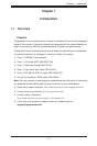
H8SCM(-F) SERVERBOARD USER'S MANUAL
2-20
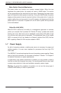
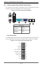
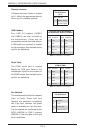
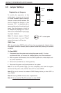
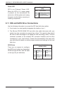
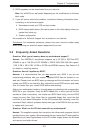
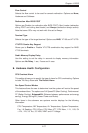
I2C to PCI-Express Slot
JI
2
C1/JI
2
C2 allows you to enable the
I
2
C bus to communicate with the PCI-
Express slot. For the jumpers to work
properly, please set both jumpers to
the same setting. If enabled, both
jumpers must be enabled. If disabled,
both jumpers must be disabled. See
the table on the right for jumper
settings.
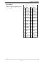
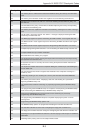
I
2
C to PCI-Express Slot
Jumper Settings
(JI
2
C1/JI
2
C2)
Jumper Setting Defi nition
Closed Enabled
Open Disabled
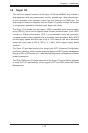
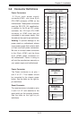
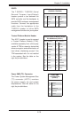
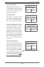
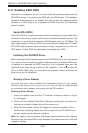
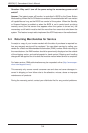
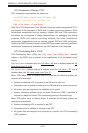
Onboard Speaker Enable/Disable
The JD1 header allows you to use
either an external speaker or the
internal (onboard) speaker. To use
the internal onboard speaker, close
pins 6 and 7 with a jumper. To use an
external speaker, remove the jumper
and connect the speaker wires to pins
4 (+5V) and 7 (control signal). See the
table on the right for settings and the
table associated with the Power LED/
Keylock/Speaker connection (previous
section) for jumper settings.
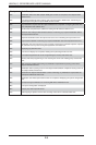
Onboard Speaker Enable/Disable
Pin Defi nitions (JD1)
Jumper Setting Defi nition
Pins 6 and 7 Jump for onboard speaker
Pins 4 and 7 Attach external speaker wires
Note: Pins 4-7 are used only for the onboard speaker.
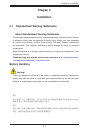
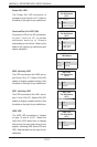
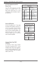
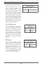
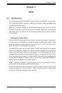
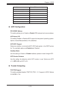
BMC Jumper
JPB1 is used to enable or disable
theBMC (Baseboard Management
Control) Chip and the onboard IPMI
connection.This jumper is used
together with the IPMI settings in the
BIOS. The default position is on pins
1 and 2 to Enable BMC. See the table
on the right for jumper settings.
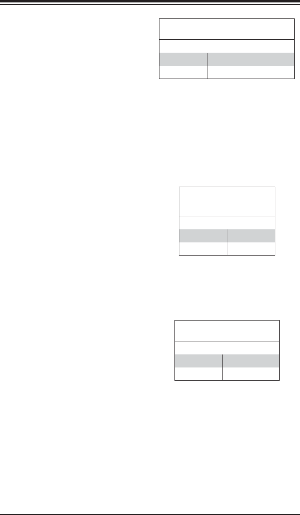
BMC Jumper Enable (JPB1)
Jumper Settings
Jumper Setting Defi nition
Pins 1-2 Enabled (default)
Pins 2-3 Disabled