H8SCM(-F) SERVERBOARD USER'S MANUAL
2-14
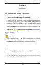
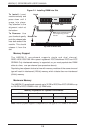
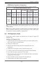
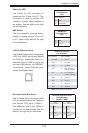
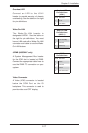
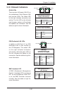
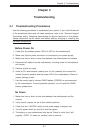
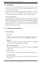
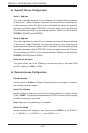
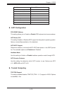
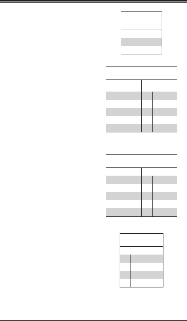
Serial Ports
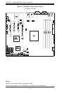
The COM1 serial port is located
beside the VGA port. Refer to the
motherboard layout for the location of
the COM2 header. See the table on the
right for pin defi nitions.
Serial Port Pin Defi nitions
(COM1/COM2)
Pin # Defi nition Pin# Defi nition
1 DCD 6 DSR
2 RXD 7 RTS
3 TXD 8 CTS
4 DTR 9 RI
5 Ground 10 NC
Note: NC indicates no connection.
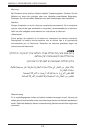
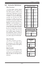
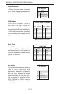
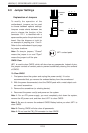
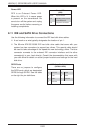
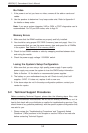
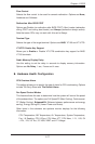
Fan Header
Pin Defi nitions
Pin# Defi nition
1 Ground
2 +12V
3 Tachometer
4 PWR Modulation
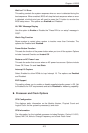
Fan Headers
This motherboard has fi ve fan headers
(Fan1 to Fan5). These 4-pin fans
headers are backward compatible
with 3-pin fans. However, fan speed
control is available for 4-pin fans only.
The fan speeds are controlled by the
BIOS (H8SCM) or IPMI if present
(H8SCM-F). See the table on the right
for pin defi nitions
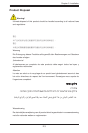
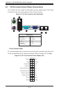
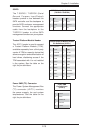
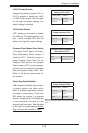
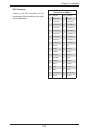
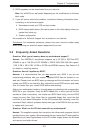
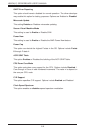
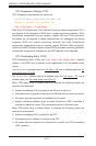
USB Headers
Four USB 2.0 headers (USB2/3
and USB4/5) are also included on
the motherboard. These may be
connected to provide front side access.
A USB cable (not included) is needed
for the connection. See the table on the
right for pin defi nitions.
Universal Serial Bus Headers
Pin Defi nitions (USB2/3, USB4/5)
USB2
Pin# Defi nition
USB3
Pin# Defi nition
1 +5V 1 +5V
2 PO- 2 PO-
3 PO+ 3 PO+
4 Ground 4 Ground
5 Key 5 NC
Note: NC indicates no connection.
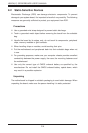
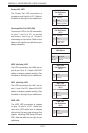
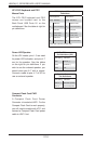
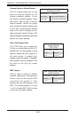
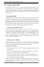
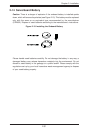
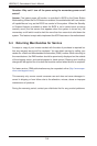
Chassis Intrusion
A Chassis Intrusion header is located
at JL1. Attach the appropriate cable to
inform you of a chassis intrusion.
Chassis Intrusion
Pin Defi nitions
(JL1)
Pin# Defi nition
1 Battery voltage
2 Intrusion signal