Chapter 2: Installation
2-13
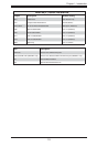
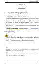
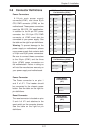
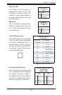
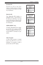
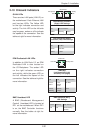
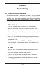
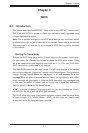
Power On LED
The Power On LED connector is
located on pins 15 and 16 of JF1. This
connection is used to provide LED
indication of power being supplied to
the system. See the table on the right
for pin defi nitions.
Power LED
Pin Defi nitions
(JF1)
Pin# Defi nition
15 Vcc
16 Power LED
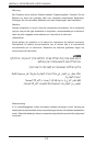
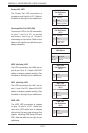
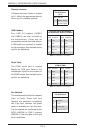
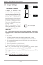
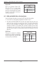
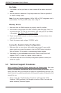
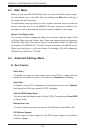
NMI Button
The non-maskable interrupt button
header is located on pins 19 and 20
of JF1. Refer to the table on the right
for pin defi nitions.
NMI Button
Pin Defi nitions
(JF1)
Pin# Defi nition
19 NMI
20 Ground
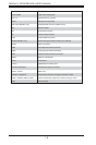
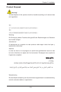
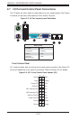
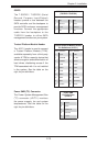
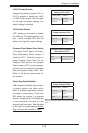
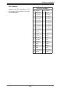
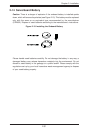
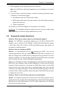
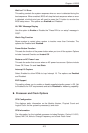
Universal Serial Bus Ports
Two Universal Serial Bus ports (USB
2.0) are located beside the Keyboard
and Mouse PS2 ports (USB0/1).
One additional Type A port (USB6) is
included on the motherboard. See the
table on the right for pin defi nitions.
Universal Serial Bus Ports
Pin Defi nitions
(USB 0/1, USB6)
USB0
Pin# Defi nition
USB1
Pin# Defi nition
1 +5V 1 +5V
2 PO- 2 PO-
3 PO+ 3 PO+
4 Ground 4 Ground
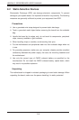
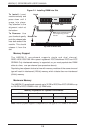
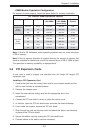
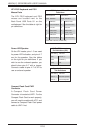
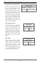
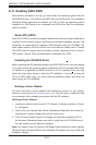
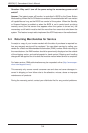
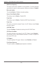
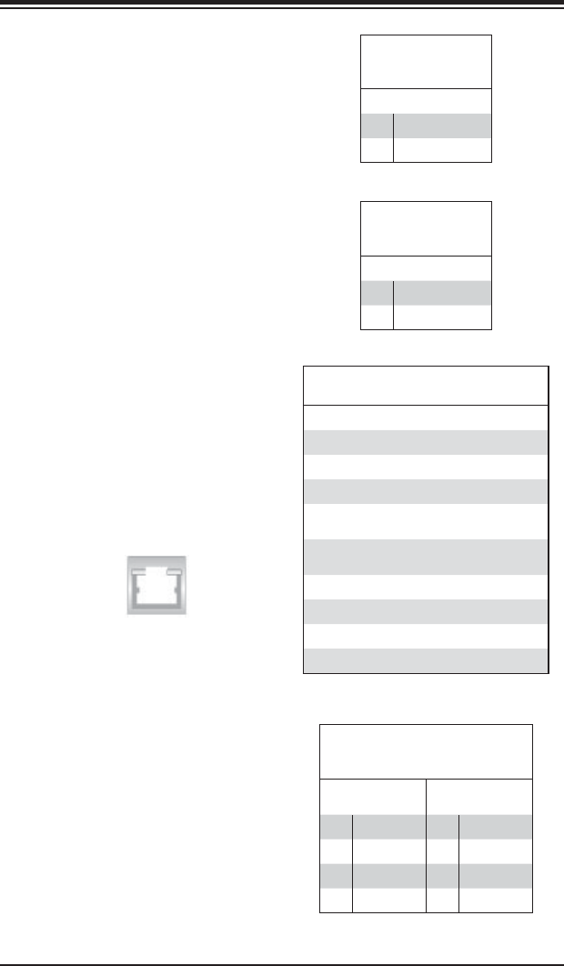
LAN1/2 (Ethernet Ports)
Two Gigabit Ethernet ports (designated
LAN1 and LAN2) are located beside
the VGA port. Additionally, there is a
dedicated LAN for IPMI on top of the
two rear USB ports for the H8SCM-F
serverboard. These Ethernet ports
accept RJ45 type cables.
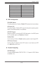
LAN Ports (LAN1/2)
Pin Defi nition
Pin# Defi nition Pin# Defi nition
1 P2V5SB 10 SGND
2 TD0+ 11 Act LED
3 TD0- 12 P3V3SB
4 TD1+ 13 Link 100 LED
(Yellow, +3V3SB)
5 TD1- 14 Link 1000 LED
(Yellow, +3V3SB)
6 TD2+ 15 Ground
7 TD2- 16 Ground
8 TD3+ 17 Ground
9 TD3- 18 Ground
Note: NC indicates no connection.