Program 10 : System Configuration Setup
10-03 : PCB Setup
44 ◆ Aspire ISDN PRI Manual
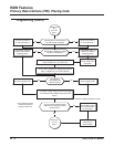
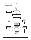
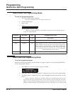
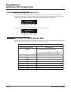
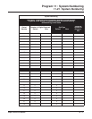
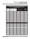
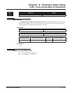
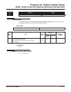
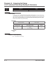
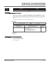
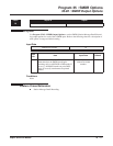
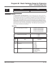
Note 1. The start port number of a PRI line is displayed. Thirty logic ports are automatically
assigned to a PRI line.
Note 2. Each timer value of Layer3 is set up for each type in Program 81-06 (T-Bus) and Pro-
gram 82-06 (S-Bus).
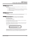
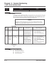
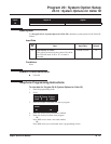
Conditions
(A.) When changing a defined terminal type, first set the type to ‘0’ and then plug the new device in
to have the system automatically define it or redefine the type manually.
(B.) The system must have a PCB installed in order to view/change the options for that type of
PCB.
Feature Cross Reference
None
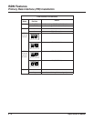
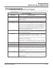
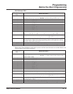
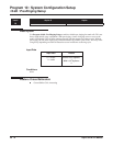
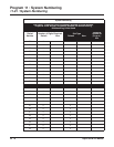
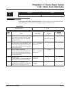
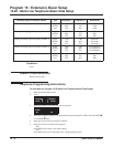
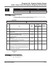
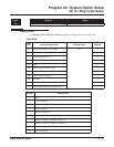
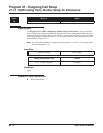
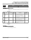
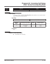
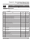
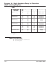
09 Dial Information Element
(Only for Overlap Sending Mode)
0 = Keypad Facility
1 = Called Party Number
0
10 Master/Slave System (Network Mode
only)
0 = Slave System
1 = Master System
0
11 Networking System Number (Net-
work Mode only)
0-50 0
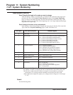
12 short / long-haul 0 = short-haul
1 = long-haul
0
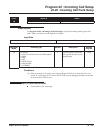
13 Loss-Of-Signal detection limit In short-haul mode
0 = 0.91V
1 = 0.74V
2 = 0.59V
3 = 0.42V
4 = 0.32V
5 = 0.21V
6 = 0.16V
7 = 0.10V
In long-haul mode
0 = 1.70V
1 = 0.84V
2 = 0.84V
3 = 0.45V
4 = 0.45V
5 = 0.20V
6 = 0.10V
7 = not defined
0
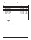
14 Service Protocol for S-Point 0 = Keypad Facility
1 = Specified Protocol for Aspire System
0
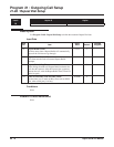
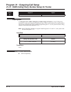
Item
No.
Item Input Data Default