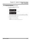
Program 10 : System Configuration Setup
10-03 : PCB Setup
Aspire ISDN PRI Manual ◆ 43
Program 10 : System Configuration Setup
10-03 : PCB Setup
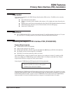
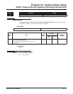
Description
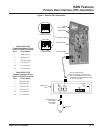
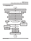
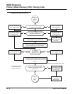
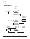
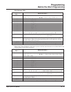
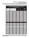
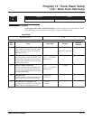
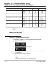
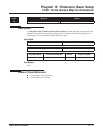
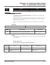
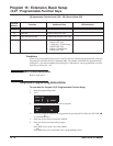
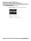
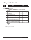
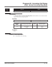
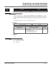
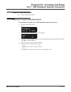
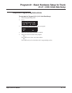
Use Program 10-03 : PCB Setup to setup and confirm the Basic Configuration data for each PCB.
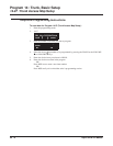
When changing a defined terminal type, first set the type to ‘0’ and then plug the new device in to
have the system automatically define it or you may have to reseat the PCB.
Note: The items highlighted in gray are read only and cannot be changed.
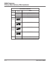
Input Data
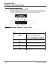
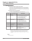
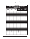
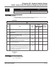
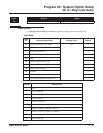
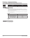
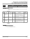
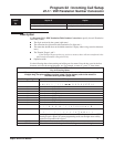
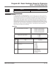
For PRIU Unit
Level:
Aspire S Aspire
IN •Available. • Available.
Item
No.
Item Input Data Default
01 ISDN Line Mode 0 = Not set
1 = T-Bus
2 = S-Bus
3 = Network Mode (Leased Line)
4 = Network Mode (Interconnected Line)
5 = Network Mode (Interconnected Line, Fixed Layer 1=NT)
6 = S-Point (Leased Line)
1
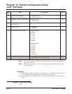
02 Logical Port Number
(see Note 1)
1 = for T-Bus 1-200
2 = for S-Bus 1-256
0
03 CRC Multi-frame(CRC4)
(Only E1[30B+D] Mode)
0 = off
1 = on
0
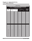
04 Layer 3 Timer Type (see Note 2) 1-5 1
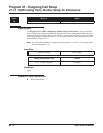
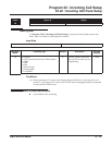
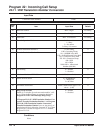
05 CLIP Information
Based on this setting, the system will
include a “Presentation Allowed” (1)
or “Presentation Restricted” (0) in the
Setup message to allow or deny the
Calling Party Number. Program
15-01-04 must also be set to a ‘1’ if
this option is enabled.
0 = Disable
1 = Enable
1
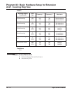
06 Length of cable 0 = 0 40m
1 = 40 81m
2 = 81 122m
3 = 122 162m
4 = 162 200m
0
07 S-Point DID Digits 0-4 0
08 Dial Sending Mode 0 = Enblock Sending
1 = Overlap Sending
0