


Electrical
requirements
Observe all governing Codes
and Ordinances.
1. A two wire, single phase, 220 Volt,
50 Hz, AC only. electrlcal power
supply IS required on a separately
fused 15 Ampere circuit (Time
delay fuse or circuit breaker is
recommended )
2. An adequate electrical ground is
required within 4 feet of the
appliance location when using the
grounding wire supplied
3. THE DRYER MUST BE CONNECTED
TO COPPER WIRE ONLY. Aluminum
wire must not be used to avoid
potentially unsatisfactory
connections.
4. Local codes may permit the use
of a flexible type electrical power
supply cord [pigtail), A suitable
strain relief must be provided at the
point the power supply cord enters
the appliance
5. The appliance may be connected
directly to the fused dtsconnect [or
circuit breaker) box through flexible
armored or non-metallic sheathed
cable. Allow two or three feet of
slack in the line between the wall
and the appliance so that it may
be moved if servicing IS ever
necessary A suitable strain relief
must be provided at each end of
the electrlcal power supply cable
[at the appliance and at the
junction box). Wire sizes and
connections must conform with
the rating of the appliance
[I5 Amperes). DO NOT use an
extension cord.
Electrical
Connection
220 Volt - Single Phase -
2-Wire Connection
Electrical ground is required on
this appliance.
This cppliance is manufactured with
the neutral terminal NOT connected
to the frame.
CONNECT GROUND
TO FUSED DIS-
II
64 Y--w
SUPPLY CORD
\ )+p\
Figure 1
POWER SUPPLY CORD
(WITH STRAIN RELIEF)
/ (15 AMPERES)
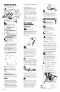
Connect the power supply cord
as follows:
1. Remove the terminal block cover
2. Connect the two wires of the power
supply cord to the outer terminals of
the terminal block. See Figure 1.
For connecting plain-end field wire,
see Figure 2
3. Replace terminal block cover,
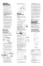
NOTE Plan-end field wires must be
fastened between the terminals of
trle terminal block and the nuts of the
terminal block screws as shown in
Figure 2.
CONNECT GROUND
WIRE TO APPROVED
GROUND
v
pk
POWER SUPPLY CORD
Figure 2
(WITH STRAIN RELIEF) ,
(15 AMPERES)
4. Connect a separate copper
grounding wire (No 10 minimum] to
a grounded cold water pipe” my
means of a clamp and then to the
frame of the appliance at the
external grounding connector. Use
Part No. 685463 grounding wire and
clomp assembly. Do not ground to
a gas supply pipe Do not connect
PANEL B
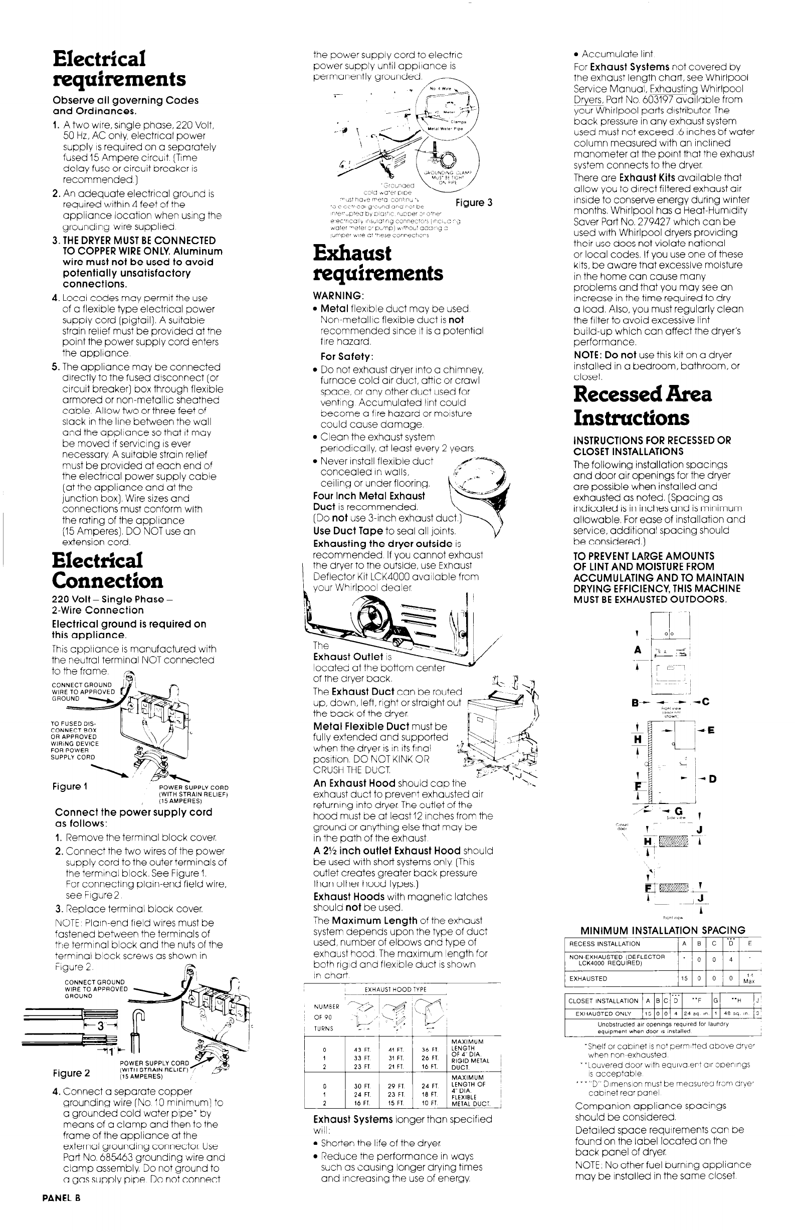
the power supply cord to electric
power supply until appliance is
permanently grounded.
Exhaust
requirements
WARNING:
l Metal flexible duct may be used
Non-metallic flexible duct is not
recommended since It is a potential
fire hazard.
For Safety:
l Do not exhaust dryer Into a chimney,
furnace cold air duct, atiic or crawl
space, or any other duct used for
venting Accumulated lint could
become a fire hazard or moisture
could cause damage,
l Clean the exhaust system
perlodically, at least every 2 years
l Never install flexible duct
concealed In walls,
ceiling or under flooring.
Four Inch Metal Exhaust
Duct is recommended.
(Do not use 3-inch exhaust duct.
Use Duct Tape to seal all joints.
Exhausting the dryer outside is
recommended If you cannot exhaust
the dryer to the outside, use Exhaust
Deflector Kit LCK4000 available from
vour WhirlDo01 dealer
of the dryer back.
The Exhaust Duct can be routed
up, down, left, right or straight out
the back of the dryer
Metal Flexible Duct must be
fully extended and supported
when the dryer IS in its final
position, DO NOT KINK OR
CRUSH THE DUCT
An Exhaust Hood should cap
exhaust duct to prevent exhausted air
returning into dryer, The outlet of the
hood must be at least 12 Inches from the
ground or anything else that may be
in the path of the exhaust,
A 2% inch outlet Exhaust Hood should
be used with short systems only, [This
outlet creates greater back pressure
than other hood types.)
Exhaust Hoods with magnetic latches
should not be used.
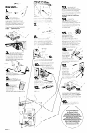
The Maximum Length of the exhaust
system depends upon the type of duct
used, number of elbows and type of
exhaust hood The maximum length for
both rigid and flexible duct is shown
In chart
EXHAUST HOOD TYPE
c--
NUMBER
I
1
1
0
43 FT 41 FT. 36 Fl
MAXIMUM LENGTH
1 33 FT 31 FT. 26 FT OF DIA 4’
RIGID METAL 2 23 FT 21 FT 16 FT. DUCT ~
I
MAXIMUM ~
0 30 FT 29 FT 24 FT LENGTH OF
1 24 FT 23 FT 1.9 FT 4” DIA I
FLEXIBLE
2 16 FT 15 FT 10 FT METAL DUCT,
Exhaust Systems longer than specified
will:
l Shorten the life of the dryer
l Reduce the performance in ways
such as causing longer drying times
and increasing the use of energy.
l Accumulate lint.
For Exhaust Systems not covered by
the exhaust length chart, see WhIrlpool
Service Manual, Exhausting Whirlpool
Dryers, Part No 603197 available from
your Whirlpool parts distributor. The
back pressure in any exhaust system
used must not exceed .6 inches 0f water
column measured with an inclined
manometer at the point that the exhaust
system connects to the dryer
There are Exhaust Kits available that
allow you to direct filtered exhaust air
Inside to conserve energy during winter
months. Whirlpool has a Heat-Humidity
Saver Part No. 279427 which can be
used with Whirlpool dryers providing
their use does not violate national
or local codes, If you use one of these
kits, be aware that excessive moisture
in the home can cause many
problems and that you may see an
increase in the time required to dry
a load. Also, you must regularly clean
the filter to avoid excessive lint
build-up which can affect the dryer’s
performance.
NOTE: Do not use this kit on a dryer
installed in a bedroom, bathroom, or
closet.
Recessed Area
Instluctions
INSTRUCTIONS FOR RECESSED OR
CLOSET INSTALLATIONS
The following installation spacings
and door air openings for the dryer
are possible when installed and
exhausted as noted. [Spacing as
indicated is in inches and is minimum
allowable. For ease of installation and
service, additional spacing should
be considered.)
TO PREVENT LARGE AMOUNTS
OF LINT AND MOISTURE FROM
ACCUMULATING AND TO MAINTAIN
DRYING EFFICIENCY, THIS MACHINE
MUST BE EXHAUSTED OUTDOORS.
MINIMUM INSTALLATION SPACING
~
1
Unobstrucled air openings requtred for laundry
equ,pmenr when door IS installed
-Shelf or coblnet IS no’ perm Yed above drye,
when non-exhausted
_ =Louvered door with eaulva.ert air ooenlngs
IS acceptable
’ _ _ “D” Dlmenslon must be measure5 from dryer
cabinet rear panel
Companion appliance spacings
should be considered.
Detailed space requirements can be
found on the label located on the
back panel of dryer.
NOTE, No other fuel burning appliance
may be installed in the same closet