


Before you start...
Thii appliance is suiiable lor mobile
home Inslallalions. The inslallatlon
of Ihe &yer
must contonn to the
Manuiachrred Home Conshuclion and
Solely Slandard, Rle 24 CFR, Part 3280
(lormerly the Federal Standard tor
Mobile Home Construction and Wely.
Tile 24, HUD, Pati 280).
For mobile home use. this appliance
MUST be fastened to the floor and
MUST be exhausted to the outside.
Order Mobile Home Installation Kit
No. 346765 from your Whirlpool dealer.
Kit includes the necessary fastening
hordware and detailed installation
instructions. Exhaust system hardwore
is also available through your
Whirloool dealer.This installation must
conform with American National
Standard, Notional Fuel Gas Code
ANSI 2223.1 latest edition. and all
local codes and ordinances. Input
ratings shown on the rating plate
(serial tag) are for elevations up to
2.m) feet. For elevations above 2.ooO
feet. ratings should be reduced at a
rate of 4% for each 1 .CJZU feet above
sea level.
E
tf the dryer is installed in 0
. confined area such as a bed
room, bathroom or closet. it must be
exhausted to the outside and
provision made for enough air for
combustion and ventilation. (Check
governing codes and ordinances.)
Also refer to the section Of this
instruction covering Recessed or
Closet Installations.
Fire Hozord
* Never install dryer up
ogoinst draperies or curtains
or on carpet.
- Keep any and all items from
falling or collecting behind
the dryer.
. Replace all access panels
before operating dryer.
Farlure to follow these
Mructions could result in a
‘ire or explosron.
. II you smell gas:
I. Open windows.
2. Don’t touch electrical switches
3. Extinguish any open flame.
4. lmmedialety call your gas
supplier.
. Do Not siore or use gasoline or
other flammable vopors and
tiauids in the vicinitv of this or
any other appliance. The
lumes can create a lire hazard
or explosion.
F .
If local codes
oermit. R is
&ommended
that flexible metal
tubing.design
certiiied by the
American Gas
Association. be used for co
the appliance to the gas supply line.
Clhe gas pipe which extends through
the lower rear of the appliance has
3/8 inch male pipe thread.)
in-line connection to the dryer.
H
Make sure that lower edges of
. the cabinet. plus the back and
bottom sides of the dlyer are free of
obstructions to permit adeauate
clearonce of air openings for
combustion air. See Recessed Area
Instructions. back page, for minimum
spacing requirements.
I
For ease of installation, operation
n
and servicing (if ever needed)
adequote space should be provided
around the dryer.
J
A l/8 inch NPT plugged tapping,
. accessible for test gauge
connection, must be ikrstalled
immediotely upstream of the gas
supply connection to the dryer.
The dryer and its individual shutoff
valve must be disconnected from the
gos supply piping system during any
pressure testing of that system at
test pressures in excess of l/2 psig
(3.45 kPa).
Gas supply
requirements
Mark on X across the letter or
number OS you complete each step.
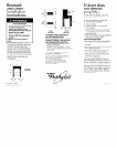
A
You need these tools to install
. your Whirlpool gas dryer. Get
Fire Hazard
- This dryer must be connected to
a reaulated oas suoolv. Failure
to do so could cause high-
pressure gas release. resulting in
0 fire or explosion.
l
Have the L.P. gas checked by a
qualified person before instolling
the dryer. The L-P. gas supply
must not exceed 0 pressure of
13” water column,
. New flexible tubing should be
used. Reusing old tlexible
tubino miaht result I” oossible
leaks-or fire hazard.
Failure to follow these tnstructions
may result in fire or explosion.
them together in one place to keep
track of them.
screwdriver
B
Check the spot where
. you’re aoina to install the
dfyer...‘proper~nstollotion IS
your responsibility.
C
Make sure you hove
. everything necessary for
proper instollotion. You’ll need:
l
To meet code requiremenlr: some
codes keen from or limtt installation
of clothes dryers in garages,
closets, mobile homes and
sleeping quarters. (Check with Your
local building inspector,)
OBSERVE ALL GOVERNING
CODES AND ORDINANCES
A
First make certain that this dryer
m is eauiooed with the correct
burner for the particular type of gas in
the home. Burner information will be
found on the rating plate in door well
of the opplionce. If this information
does not agree wit the type of gas
available. see your dealer,
The dryer must be isolated from the
gas supply piplng system by
closina its individual manual shutoff
vaiveduring any pressure
testing of the gas supply piplng system
at test pressures equal to or
less that l/2 psig (3.45 kPa).
Important: Observe all govemlng
codesandordinances.
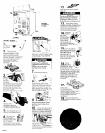
K
The dryer shutoff valve and the
. wiring diagram are located
behind the lower front access panel.
Open the access panel by pushing
down on the locklna CIIDS with a small.
Important: Observe all governing
codes and ordinances.
. To check utilities: proper gas ond
electric supply connections
should be available.
l
To check exhaust requirements:
a four inch metal exhaust duct
is required.
B
This dryer is
=equipped for
use with NATURAL GAS.
It is certified bv A.G.A.
i
for manufactured. mixed ond L.P.
gases with appropriate conversion,
No attempt shall be made to convert
the aDpliance from the aas SDeCKied
on therating plate for u& wrth a
different gas wtthouf consuiting the
serving gas supplier. ConversIon
musl be done by a qualiiied service
technician. Gas converslon kit part
numbers are listed on the gas valve
burner base.
C
Provide a gas supply line to the
n
dryer location. When rigid pipe
is used it should be l/2 inch IPS. When
acceptable to the gas supplier, 3/8
inch approved tubing may be used
for lengths under 20 feet. For lengths
over 20 feet. lorger tubing should be
used. Pipe joint
COmDOundS
resistant
flat-blade screwdriver, and pulling
panel forward. The clips are located
on top of the panel 3 inches In from
each side. The aanel is hinaed at the
bottom. Close ihe access cane1 after
serviclng. Do Not operate the dryer
with the access panel open.
L
If drYer will not operate, check
. the following to be sure that
1. Electric supply is connected.
2. Fuse is intact and tight.
3. Door is closed.
4. Controls are set in 0 running or
*On % position
5. Start button has been pushed
firmly or the power control iever
moved upward to start.
6. Gas shutoff valves are open both
on drver and on SUDDIV lines.
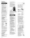
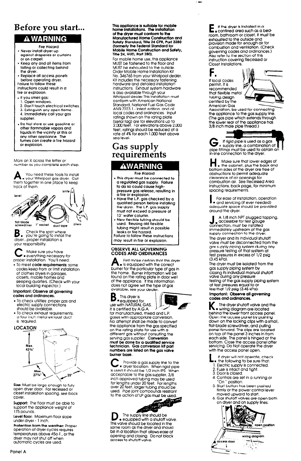
Size: Must be large enough to fully
open dryer door. For recessed or
closet installation spacing, see bock
cover.
Support: The floor must be able to
support the appliance weight of
175 pounds.
Level floor: Maximum floor slope
under dryer - 1 inch.
Protection from the weather: Proper
operation of dryer cycles requires
temperatures above 450 F.. or the
drver mov not shut off when
automatic cycles ore used
to the octidn of LP gas
D
The supply line should be
. equipped with a shutoff valve.
This valve should be located in the
some room as the dryer and should
be in a location that allows ease of
opening ond closing. Do not block
access to shutoff valve.
Panel A