


9
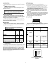
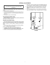
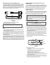
ADAPTING LINE OUT TO DUAL BANANA JACK
Add a dual banana jack, balanced, line-level output capability by
purchasing a commercial unit (Sescom XLR F-3BP or equivalent),
or obtaining a female XLR connector (Radio Shack 274-011 or
equivalent), a dual banana jack (ITT 2269 or equivalent), a small
utility box, and a short length of high-quality shielded output cable
and constructing the adapter shown in Figure 6.
DUAL BANANA JACK OUTPUT
FIGURE 6
Connect this adapter to the M367 Line output.
CHANGING MONITOR IN TO AUX IN
Remove resistors R642 and R647 (near Phones potentiometer
R648).
Locate empty pads X601 (near output transformer T601) and
X643 (near Monitor In jack J683).
Solder a jumper wire from X643 to X601. The Monitor In jack is
now an unbalanced (tip positive, sleeve ground) Aux In jack, with
an input impedance of 11 kΩ and a maximum gain to Line Out
(loaded with 600 Ω) of 17 dB. The Aux In signal is only controlled
by the Master control.
To change Aux In gain, locate resistor R605 (near X601). Care
fully remove R605 and replace it with a surface-mount resistor
(0805 package) of the desired value. If replacing R605 with 15 kΩ,
maximum Aux In to Line Out gain equals 14 dB and input
impedance equals 16 kΩ; if replaced with 6.8 kΩ, maximum Aux In
to Line Out gain equals 20 dB and input impedance equals 7.8 kΩ.
CHANGING MONITOR IN HIGH GAIN (DIP Switch S701
Position 5 Down)
Locate resistor R647 (near Phones potentiometer R648) and re-
move it. Locate empty pads X647 (near R647). Solder a 330
Ω
,1/4 W
resistor in the holes of X647 for 6 dB gain boost with DIP switch S701
position 5 down (input impedance equals 6.5 k
Ω
in this position).
CHANGING MONITOR IN JACK FROM MONO INPUT TO
STEREO SUM INPUT
Locate empty pads X645 (near Monitor In jack J863). Solder a
1 kΩ, 1%, 1/4 W resistor in the holes of X645. The Monitor In jack
will now accept a stereo input signal (tip left, ring right, sleeve
ground), and sum these signals to the monitor circuit.
MASTER GAIN REMOTE CONTROL
1. Remove resistor R641 (near Monitor In jack J863).
2. Remove resistor R746 (near Master potentiometer R706).
3. Locate empty pad X702 (near Master potentiometer R706).
Solder one end of a 100 Ω, 1/4 W resistor in the hole of X702.
Solder an insulated wire to the other end of the 100 Ω resistor.
Locate empty pad X644 (near jack J863). Solder the other end
of the insulated wire to X644.
4. Locate empty pad X701 (next to empty pad X702). Solder an
insulated wire to X701. Locate empty pads X645 (near jack
J863). Solder the other end of the insulated wire to the empty
pad X645 nearest channel 6 input connector J856.
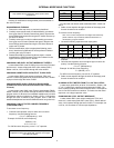
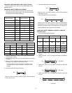
5. Construct a remote control potentiometer/cable assembly as
shown in Figure 7.
MASTER GAIN REMOTE CONTROL
FIGURE 7
Recommended parts are:
Potentiometer, 10-25 kΩ, linear taper (Radio Shack
271-1715)
1/4 in. Stereo Phone Plug (Switchcraft 280)
Ferrite Bead Rings (Ferronics 21-031J)
Capacitors, ceramic, 0.001 μF, 50 V
Cable, 2-conductor, shielded, 50 ft maximum (15 m)
Ferrite bead rings and capacitors should be as close to the
phone plug as possible.
6. Insert the phone plug in the Monitor In jack. The remote con-
trol potentiometer now controls M367 gain with a control taper
similar to that of the Master gain control.
NOTE:
This modification disables the M367's monitor function.
2
3
1
NOTE
If using a true stereo feed to drive the M367 Monitor In and
another stereo device, the source impedance must be 20 Ω or
less to maintain at least 40 dB separation in the stereo device.
Use a stereo distribution amplifier or buffer to maintain optimum
stereo separation.
NOTE
This modification disables both the M367's monitor function and
its front-panel Master gain control.
CW
TIP
RING
SLEEVE