


3
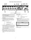
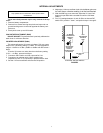
REAR PANEL CONNECTORS AND CONTROLS
REAR PANEL CONNECTORS AND CONTROLS
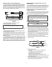
FIGURE 2
1. Mic/Line Level Output Switch: Sets output to microphone or
line level.
2. Phantom Power Switch: Adds 12-volt phantom power to all
inputs set to MIC. Use DIP switch 7 to increase voltage to 48
volts (see DIP Switches).
3. Mic/Line Level Input Switches 1-6: Sets input to microphone
or line level. Phantom power is disabled for inputs set to LINE.
4. M267/M367 Mix Bus Level Switch: Set to M267 when con-
necting to a SHURE M267, FP42, FP51, M67, or SE30. Use
the M367 setting with another M367 or SHURE FP32A.
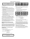
5. Mix Bus Jack: Allows you to connect the M367 to another
mixer. The mix bus connection is "two-way" and pre-master.
When two M367 mixers are connected, all 12 inputs appear at
both mixers' outputs. The MASTER gain control of either
M367 can be adjusted without affecting the other mixer’s
output.
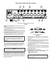
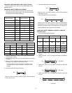
For a balanced mix bus connection between two M367s, use a
mix bus cable with two 1/4 in. stereo (tip, ring, sleeve) plugs.
When connecting other types of Shure mixers, construct a mix
bus cable with a 1/4 in. mono phone plug (tip = signal, sleeve =
ground) and the appropriate connector for the other mixer's mix
bus jack (see Figure 3).
MIX BUS CONNECTIONS
FIGURE 3
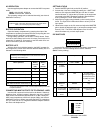
6. Channel Inputs: These female XLR inputs are transformer-
balanced to provide superior rejection of hum, RFI, and other
interference.
7. Monitor In Jack: Accepts mono line-level signals (tip = signal,
sleeve = ground) for "tape return" or a communications chan-
nel input. See Pull/Monitor switch description.
You can also modify the MONITOR IN jack to accept a stereo
input and provide a stereo sum monitor signal (see Internal
Modificable Functions).
8.
Mixer Output:
These male XLR outputs are transformer-balanced.
The Line output is preset to line level, but can be modified to a true
600
Ω
output impedance or changed to microphone level (see Inter-
nal Modifiable Functions).
9. Power Connector: See AC Operation.
10. Time Delay Fuses: The slide-out compartment contains two
power line fuses. The outer (toward you) is a spare.
M367: 0.125A, 250V fuse
M367E: 0.063A, 250V fuse
LINEMIC LINEMIC LINEMIC LINEMIC
LEVEL
M267 M367
LINE
LINE
MIC LINE PHANTOM
IN
MONITOR
OFF ON
MIC LINE MIC
100-120 VAC 50/60 Hz 100 mA
INPUT
4321
MIX
BUS
5
OUTPUT
6
1 2 3 4
9
8
7 6 5
SPARE
10
IMPORTANT
Unless required, leave the mix bus LEVEL switch in the
M367 position. The M367 setting may increase mixer out-
put noise up to 30 dB, depending on the MASTER output
setting.
NOTE
The output level of each M367 mixer drops by 6 dB when connected
through the MIX BUS, increase the Master Gain to compensate.
BALANCED
UNBALANCED
TO M367 #1 TO M367 #2
TO M367 TO M267
N.C.
WARNING
For continued protection against fire, replace with the same
type and rating of fuse.