


5
SPECIFICATIONS
Frequency Response
20 to 20,000 Hz ± 2.0 dB (channel controls centered)
Total Harmonic Distortion
0.25% THD at +4 dBm output, 55 to 20,000 Hz
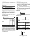
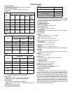
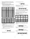
Voltage Gain
Inputs
Outputs
Equivalent Input Noise
≤ –127 dBV with 150 Ω source, 400 to 20,000 Hz
Output Noise
Master level full CCW: –100 dBV, 400 to 20,000 Hz
Master level full CW: –80 dBV, 400 to 20,000 Hz
Hum and Noise
Equivalent Input:
≤125 dBV, 20 to 20,000 Hz
Output: –95 dBV (Master CCW), –75 dBV; (Master CW), 20 to
20,000 Hz
Common Mode Rejection Ratio
65 dB at 100 Hz, –20 dBV input
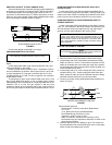
Polarity
Overload and Shorting
Shorted outputs, even for prolonged periods, cause no damage.
Microphone inputs of up to 3 Vrms cause no damage. Line and
monitor can withstand signals of up to 30 Vrms.
Input Peak Indicators
6 dB below clipping level
Output Peak Indicator
Lights red at 6 dB below clipping level
Output Clipping Level
≤ +18 dBm at line output into 600 Ω
Low-Cut Filters
7 dB down at 150 Hz; 6 dB/octave slope (3 dB down at 260 Hz)
Tone Oscillator
1 kHz ± 20%
Limiter
Threshold: Switchable: 0, +4, +8, +16 dBm
Attack Time: 1 ms ± 0.5 ms
Release Time Constant: 100 ms ± 30 ms
Indicator: Green when limiting by 1 dB or more
Phantom Power
12 V Phantom: 12 V through 340 Ω
48 V Phantom : 48 V through 3.4 kΩ
AC Power
M367: 100–120 Vac, 50/60 Hz, 100 mA
M367E: 220–240 Vac, 50/60 Hz, 50 mA; no-signal current drain
25 mA
DC Power
18 Vdc nominal at 40 mA typical no-signal, 45 mA typical at +4
dBm output; 13.5 Vdc minimum
Batteries
Two 9 V alkaline batteries
Battery Life
Up to 8 hours* at +4 dBm output in continuous use.
*(see Battery Operation)
Temperature Range
Operating: -18° to 57° C (0° to 135° F)
Storage: -29° to 74°C (-20° to 165° F)
Overall Dimensions (H x W x D)
71.9 mm x 308 mm x 233 mm (2 13/16 in. x 12
5/32 in. x 9 5/32 in.) including feet.
Weight (without batteries)
3 kg (6.6 lb)
Measurement conditions (unless otherwise specified): operating
voltage 120 Vac, 60 Hz (18
±
1 Vdc for dc test); operating tempera-
ture 22°C (72°F); input signal 1 kHz; internal DIP switches 1–7 open;
Power switch on; Mic/Line switches to Line; low-cut switches to flat;
Limiter out; Phantom power off; Mix Bus to M367; channel 1 gain full
CW; channel 2 through 6 full CCW; Master full CW; Phones level full
CCW; Line output terminations 600
Ω
(pins 2 and 3); Mic output ter-
minations 150
Ω
(pins 2 and 3); Phones (1/4"–ring) 300
Ω
to ground;
Phones (1/4"–tip) 300
Ω
to ground; Phones (3.5 mm) unloaded; Mix
Bus 930
Ω
(M367 position) or 3.5 k
Ω
(M267 position), not connected
unless specified; 1 kHz input signal.
Output
Input
Line Mic Phones
Mix Bus
(M367)
Mix
Bus
(M267)
Low-Z Mic
(150
Ω
)
87 dB 40 dB 103 dB 66 dB 27 dB
Line
37 dB -11 dB 53 dB 15 dB -25 dB
Monitor
--
--
12 dB -- --
Mix Bus
(M367)
10 dB -38 dB 26 dB -- --
MixBus
(M267)
50 dB 2 dB 66 dB -- --
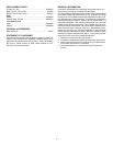
IMPEDANCE Input
Input
Designed for
Use With
Actual
(Internal)
Clipping
Level
Mic 19 to 600 Ω 1 kΩ -10 dBV
Line ≤10 kΩ 50 kΩ +36 dBV
Monitor ≤1 kΩ 13 kΩ 0 dBV
Mix Bus
(M367)
930 Ω bal.;
1860 Ω unbal.
930 Ω bal.;
1860 Ω unbal.
+23 dBV
Mix Bus
(M267)
3.5 kΩ 3.5 kΩ -17 dBV
IMPEDANCE Output
Output Designed for
Use With
Actual
(Internal)
Clipping
Level
Mic Low-Z inputs 1 Ω -31 dBV
Line 600 Ω 150 Ω +18 dBm
Phones 8 to 200 Ω 300 Ω +11 dBV
Mix Bus
(M367)
930 Ω bal.;
1860 Ω unbal.
930 Ω bal.;
1860 Ω unbal.
+11 dBV
Mix Bus
(M267)
3.5 kΩ 3.5 kΩ -28 dBV
Mic/Line In to Mic/Line Out Non-Inverting
Mic/Line In to Phones Non-Inverting
Mic/Line In to Mix Bus (tip) Inverting
Monitor to Phones Non-Inverting
Mix Bus to Mic/Line Out Inverting