,
INSTALLATION
GAS CONNECTION (Gas dryers only)
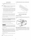
a. Remove the shipping cap from gas pipe at the rear of the
dryer.
NOTE: DO NOTconnect the dryer to L.R gas service without
converting the gas valve. An L.R conversion kit must
be installed by a qualified gas technician.
b,
Connect a 1/2 inch (1.27 cm)I.D, semi-rigid or approved
pipe from gas supply line to the 3/8 inch (0.96 cm) pipe
located on the back of the dryer. Use a 1/2 inch to 3/8
inch (1.27 cm to 0.96 cm) reducer for a connection. Apply
an approved thread sealer that is resistant to the corrosive
action of liquefied gases on all pipe connections.
c. Open the shutoff valve in the gas supply line.
d. Testall connections by brushing on a soapywater solution.
NEVER TESTFOR GAS LEAKS WITH AN OPEN FLAME.
2. Connect the exhaust duct to outside exhaust system. Use
duct tape to seal all joints.
,
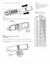
With the dryer in its final position, adjust one or more of the
legs until the dryer is resting solid on all four legs. Place a
level on top of the dryer. THEDRYER MUSTBE LEVELAND
RESTING SOLID ON ALL FOUR LEGS.
4. Plug the power cord into a grounded outlet. NOTE:Check
to ensure the power is off at circuit breaker/fuse box before
plugging the power cord into the outlet.
5. Turn on the power at the circuit breaker/fuse box.
Before operating the dryer, make sure the
dryerarea is clear and free from combustible materials,
gasoline, and other flammable vapors. Also see that nothing
(suchas boxes,clothing, etc.) obstructs the flow of combustion
and ventilation air.
,
Run the dryer through a cycle check for proper operation.
NOTE: On gas dryers, before the burner will light, it is
necessaryfor the gas line to be bled of air. If the burner does
not light within 45 seconds the first time the dryer is turned
on, the safety switch will shut the burner off. If this happens,
turn the timer to "OFF" and wait 5 minutes before making
another attempt to light.
7. Placethese instructions in a location near the dryer for future
reference.
NOTE: A wiring diagram is located inside the dryer.
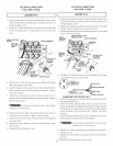
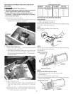
Lint Blade Retaining Pin Location and Orientation
/
Install the pins after the lint blade is installed.
METER CASE INSRUCTIONS
COIN BOX ADJUSTMENT
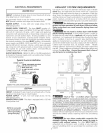
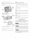
The tight fit of the money box is set at the factory. Customer
may loosen fit as desired by loosening the slotted nuts. See
FIG.1.
FIGURE
Keep A record of all coin-box key numbers. A lost key can
only be replaced by ordering the key numbers from the place
were the unit was purchased. The key number is located both
on the key and behind the end panel of the coin box. If the key
number is not available, the lock must be drilled out to remove
the coin box.
9


