


HURSPK0026/00186
Page 5 of 21
Reconnect the left-hand uplock jaw and shaft-lock together using the new lock-nuts
provided in the kit and the existing bolts (only hand tighten these bolts at this time).
44. Replace the lock shaft through the cross-member, being careful to put the correct spacers
in the correct position and making sure that the uplock is in its original position.
45. Replace the lock shaft bearing and re-bolt to the cross-member using the new lock-bolts
provided in the kit. Replace spacers on shaft.
46. Replace left-hand assembly bracket onto shaft and hand tighten lock shaft lock bolt
(provided in kit). Reconnect the bracket to the uplock bracket clevis and to the air
cylinder clevis. Tighten lock shaft bolt.
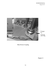
47. Remove the dome full-up contact switch bracket from the upper cross-member to the
right of the uplock bracket assembly (See Figure 11).
48. Rotate the dome full-up contact switch bracket 180 degrees and re-bolt to upper cross-
member using new lock bolts included in the kit.
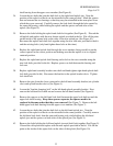
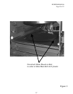
49. Remove dome full-up contact switch from the bracket and re-bolt to the opposite side of
the bracket so that the contact switch is on the discharge side of the bracket using new
lock bolts included in the kit (Correct Positioning of bracket and switch is shown in
Figure 12).
50. Manually operate the dome to the “up” position.
51. Remove the shims from the bed of the press. Replace these shims into the kit with the
rest of the shims. These shims may be needed later when shimming the downlocks.
52. Reinstall the diaphragm with the new expansion ring into the dome.
53. Turn on the 2-Stage press and manually operate the dome to the “up” position.
54. Tighten the nuts on the main bell air cylinder bolts.
55. Using manual functions, lower the main bell onto the bed.
56. Extend the down locks.
57. De-energize press power and lock off at main disconnect.
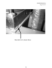
58. Check the “B” clearance between the top surface of the lock segment closest to the
discharge end of the press and the bottom surface of the lock ring (see Figure 13). Take
three (3) measurements - one (1) at each end, and one (1) in the middle of the segment.
This is the most critical segment and must be shimmed first.
12