


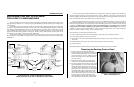
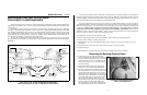


ÊMeasuring Unmounted Clearance and
Setting Bearing (Front or Rear)
The bearings used on Milnor
®
washer and dye extractors are the very best anti-friction devices available for
these applications. However, the anti-frictional characteristics of the bearings will be reduced if they are not proper-
ly installed. It is of critical importance when installing these tapered roller bearings, to accomplish the following (A
step by step procedure follows this synopsis):
1. Accurately measure the unmounted internal clearance of the bearing (gap between the rollers and outer race
before the bearing is installed). This is an essential quality control measure.
2. Calculate the final internal clearance by subtracting the specified clearance reduction (amount that the internal
clearance must be reduced when the bearing is tightened onto the tapered shaft) from the unmounted
clearance.
3. Tighten the bearing onto the shaft until the final internal clearance as calculated is achieved and verified by
measurement.
These measurements are taken in thousandths of an inch. Although this requires precise work, attention to
detail and a good set of feeler gauges, it is the only way to insure that the bearing will be tightened onto the shaft to
precisely the right tension. If you have any questions on performing the measurements or adjustments described
below, your local bearing supplier or the Milnor
®
factory can assist you. Although these procedures require
precision over and above that normally required for laundry room maintenance, they are standard in bearing instal-
lation and absolutely essential:
NOTE: Step 1 which follows, requires a good set of feeler
gauges including .001" through .010" in thousandths of an inch
increments. Contact your local bearing supplier.
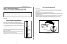
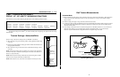
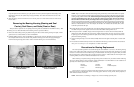
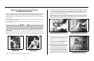
1. When you are ready to proceed (and not before) remove the
new bearing from it’s box or protective wrapping. Do not at-
tempt to clean the bearing or wash out the preservative coat-
ing. On a clean work surface, stand the bearing on edge and
insert a .003 feeler gauge into the bearing as shown in FIG-
URE 10, at right. The gauge should be inserted just inside
the outer race between two rollers and worked through to the
opposite row of rollers. Rotate the inner race of the opposite
row so that the end of the feeler gauge is caught between a
roller and the outer race.
2. Try to pull the gauge straight out. If it comes out, increase the
size of the gauge by .001". If it does not come out, decrease
the gauge by .001". The thickest feeler gauge that will come
out is the unmounted internal clearance of the bearing.
3. Compare the measured clearance with the “Unmounted Clearance” in the table below. If the measured
clearance is not within the range shown, do not use the bearing. Contact your bearing supplier for an ex-
change.
NOTE 1: The clearances listed in the chart are industry standards and therefore apply to all brands of
bearings supplied by Milnor
®
. If other sources of bearings are used, refer to the manufacturer’s instructions
for proper clearances.
NOTE 2: To locate your bearing on the chart, match the first five characters of the manufacturer’s part
number (not the Milnor
®
part number) with those in the chart. For example, for a manufacturer’s part
number 22217LBK, find under “Manufacturer Part Number” the line “22217 . . .”
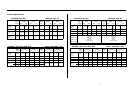
ÏTable of Bearing Clearances
4. Calculate and record the final internal clearance by deducting the “Clearance Reduction” for your bearing (see
above chart) from the measured clearance. For example, if you measured .004 and the clearance reduction is
.001 to .002, then the final internal clearance should be between .002 and .003.
5. Hand pack the bearing with grease by rotating the inner race and rollers, forcing grease between all rollers.
NOTE: The bearing will be set into position in Step 6. If both front and rear bearings are being installed,
the rear (clean side on Staph-guard
®
models) bearing should be set in position first because it is the fixed
bearing.
6. Set the bearing into the housing (with the taper facing the proper direction) and seat the bearing using the bear-
ing setting fixture. This fixture is installed in similar fashion to the seal sleeve setting fixture. If you have
just set the rear bearing and the front bearing housing is yet to be installed, leave the bearing setting fixture
in place for now.
7. If you have just set the rear bearing and the front bearing housing is yet to be installed, repeat all steps in bear-
ing housing installation, measuring unmounted clearance and setting bearing, for the front bearing and hous-
ing. The bearing setting fixture should not be removed from the rear housing until it is needed to seat the
front bearing. This will prevent rear bearing components from being pushed out of position by the shaft as
the front housing components are seated. Remove the bearing setting fixture from the front housing once the
bearing is seated.
ÎFIGURE 10 (MSSM0303AE)
ÎMeasuring Bearing
Unmounted Clearance
(bridge for 42" machine shown)
Manufacturer Part Number
Unmounted Clearance Clearance Reduction
Minimum Maximum Minimum Maximum
22330 . . . .0071 .0091 .002 .003
22213 . . . .0030 .0039 .001 .002
22216 . . . .0028 .0037 .001 .002
22217 . . . .0044 .0057 .0015 .0025
22312 . . . .0030 .0039 .001 .002
22316 . . . .0037 .0049 .001 .002
22320 . . . .0044 .0057 .0015 .0025
22328 . . . .0063 .0081 .002 .003
23220 . . . .0044 .0057 .0015 .0025
16