


Component Testing Procedures
!
WARNING
To avoid risk of electrical shock, personal injury or death; disconnect power to washer before servicing, unless
testing requires power.
16026882 2 June 2006
RPL 16026127
©2006 Maytag Services
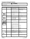
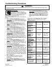
NOTE: See “Machine Control Board” on next page for pin and connector locations.
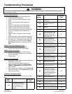
Illustration Component Test Procedure Results
Thermistor Unplug harness connector and test
from wire insertion side of connector.
Pin #6 and Pin #3 of CN3.....................
13K ohms @ 70F/21C (2.5V DC)
Door Switch Check voltage at Pin #6 and Pin #4 of
CN3.....................................................
Unplug harness connector and test
from wire insertion side of connector.
Pin #7 of CN10 and Pin #3 of CN5......
Pin #8 of CN10 and Pin #3 of CN5......
Door Open = 5V DC
Door Closed = 0V DC
60 ohms
60 ohms
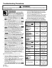
Water Sensor Check voltage and frequency at Pin #6
and Pin #7 of CN3...............................
Check voltage and frequency at Pin #6
and Pin #8 of CN3...............................
Reset water level = 2.5V DC, 25.8 KHz
Reset water level = 2.5V DC, 25.8 KHz
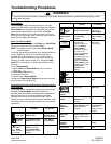
Sump Sensor
Check voltage at Pin #4 and Pin #3 of
CN8.....................................................
0V DC or 3.75V DC
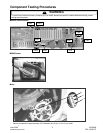
Motor
Unplug harness connector and test
from wire insertion side of connector.
Pin #1 and Pin #2 of CN9....................
Pin #1 and Pin #3 of CN9....................
Pin #2 and Pin #3 of CN9....................
Any 2 Pins (1,2,3) on Motor Connector
3.0 ohms
3.0 ohms
3.0 ohms
3.0 ohms
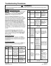
Drain Pump During drain check voltage at Pin #1 of
CN5 and Pin #6 of CN10.....................
120V AC
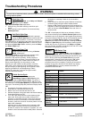
Water Valves Check voltage at Pin #1 and Pin #1,2,4
of CN10...............................................
Unplug harness connector and test
from wire insertion side of connector.
(Pre valve) Pin #3 of CN10 and Pin #2
of CN7.................................................
(Hot valve) Pin #2 of CN10 and Pin #2
of CN7.................................................
(Bleach valve) Pin #4 of CN10 and Pin
#2 of CN7.....................
(Main valve) Pin #1 of CN10 and Pin
#2 of CN7............................................
120V AC when each valve operates
1100 ohms
1100 ohms
1100 ohms
1100 ohms
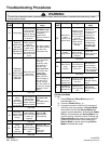
AC Power Check voltage at Pin #1 and Pin #3 of
CN5.....................................................
Check voltage at Pin #1 of CN5 and
Pin #1 of CN6......................................
120V AC
120V AC
Heater Relay During water heat check voltage at Pin
#1 of CN5 and Pin #2 of RY9...............
120V AC
Reactor Unplug harness connector and test
from wire insertion side........................
Less than 1 ohm
MEMS Sensor Check voltage at Pin #1 and Pin #5 of
CN11...................................................
Check voltage at Pin #1 and Pin #4 of
CN11...................................................
Approximately 2.5V (2.2V – 2.8V)
Approximately 2.5V (2.2V – 2.8V)