


Packing Replacement Procedures
19
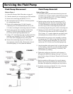
Fluid Pump Removal - Refer to Figure 1
1. Follow the Pressure Relief Procedure on page 9.
2. Flush material you are spraying out of the machine.
3. Remove the connecting rod shield (331-111).
4. Move the piston rod (331-093) to its lowest position by
cycling pump slowly.
5. Remove the retaining ring (331-062) from the connecting
rod (331-038) and slide the sleeve (331-117) down
revealing the connecting rod pin (331-065).
6. Remove the suction tube assembly from the uid pump
(331-209) by unscrewing the suction nut (331-034) with the
packing adjustment tool.
7. Using a 1/2” wrench unscrew the two bolts (100-318) from
the cover assembly (331-234). The uid pump (331-209)
will be hanging loosely at this point.
8. Remove the connecting rod pin (331-065) out of the
connecting rod (331-038), allowing the removal of the uid
pump (331-209) from the machine.
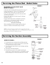
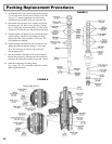
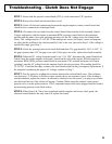
Disassembly of the Fluid Pump - Figure 6
1. Unscrew & remove the packing nut (331-037).
2. Push the piston rod (331-708) down through the packings
& out of the pump.
3. Now push the packing removal tool (331-465) up through
the pump & remove from the top bringing packings, spacer
& springs along with it, leaving uid body (331-011) empty.
*Make sure all old packings & glands have been removed from uid pump.
4. Clean inside of uid body (331-011).
5. Disassemble all parts & clean for reassembly. Discard any
old packings.
6. Lubricate leather packing in lightweight oil for 10 minutes
prior to reassembly.
Disassembly of the Outlet Valve - Figure 3
1. Place piston holder (331-195) in a vise. Slide piston into the
holder & lock in place with a 3/8” dowel.
2. Use a 1/4” allen wrench to unscrew the outlet seat retainer
(331-026) from the piston.
3. Remove the outlet seat (331-026), O-ring (331-100) and
outlet ball (331-027).
4. Inspect outlet ball & seat for wear. Replace as necessary.
5. While piston is still locked in the holder, install parts back into
the piston in the following order:
ball, outlet seat and O-ring
Before reinstalling the outlet seat support, apply two drops of
Loctite No. 242 (blue) on the threads & torque to 20 ft-lbs.
Replacement Instructions:
(
(
(
REASSEMBLY - Figure 5 & 6
1. Take lower male gland (331-014) & place it down on
the at side.
2. Take three of the lower polyethylene packings (331-016) & two
of the leather packings (331-306) & place onto the male gland in
the following order with the inverted side down :
Polyethylene, leather, polyethylene, leather, polyethylene.
3. Take the female adaptor (331-305), which is inverted on both
sides , & place it on top of your assembled lower packings.
4. Follow step 2 above with your packings inverted side up.
5. Take the second lower male gland and place it on top of your
assembled packings with the rounded side down.
6. Take assembled glands & packings (13 pieces) & slide on to the
lower half of the piston.
7. Take the spacer (331-018) & slide over the top of the piston (it
doesn’t matter which direction it sits), falling onto lower packings.
8. Take three Belleville Springs (331-025) & slide over the top of
the piston in the following order:
* First spring, curve facing down
* Second spring, curve facing up
* Third spring, curve facing down
9.
Take the upper male gland (331-022) & place it rounded side up.
10. Take three upper polyethylene packings (331-023) & two leather
packings (331-307) & assemble with inverted side down ,
on to the male gland in the following order:
polyethylene, leather, polyethylene, leather, polyethylene.
11. Take upper female gland (331-021) & place on top of the assembled
upper packings with the inverted side down.
12. Take assembled upper glands & packings (7 pieces) & slide on
over the top of the piston, making sure inverted sides are down.
13. Take the packing holder (331-019) & replace the white O-ring
(106-009) & the black O-ring (106-010) with new ones from the
packing kit.
14. Slide the packing holder over the top of the upper packings
so they t inside.
15. Lubricate inside of the uid pump body & the outside of the
packings with a light weight oil.
16. Slide completed assembly into uid pump body (331-011).
* To keep packings secured in correct position, hold the pump body
upside down & push the completed assembly upwards into the pump
body. Once placed inside, tilt pump body back up to keep all pieces in.
17. Tighten packing nut (331-037) onto the top of the uid pump
body & tighten until you feel slight resistance against the
Belleville Springs (331-025). Using the Packing Adjustment Tool
(189-211), tighten another 3/4 of a turn.
Fluid Pump Reinstallation -
Figure 1 & 4
1. Loosen packing nut & ensure that the piston rod (331-093) is in
its upper position in the uid pump body (331-011). Slip the
sleeve (331-117) & the retaining ring (331-062) over the piston rod.
2. Push piston rod up into the connecting rod (331-038) & align the
holes. Insert the connecting rod pin (331-065) through the
connecting rod & piston. Slip the sleeve up over the connecting
rod pin & insert retaining ring into the groove on the connecting rod.