


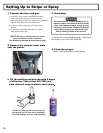
1. Choose handle location
The choices are, installing the handle opposite of the
single wheel assembly (standard set up) or placing
the handle directly over the single wheel assembly.
The handle location is really a matter of personal
preference, however having the handle away from
the single wheel assembly allows for easier loading/
unloading from a van or truck.
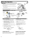
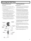
2. Cable Tension Adjustment
Once the handle and gun arm assemblies are set up to
the preferred positions, pressurize the unit and trigger
each gun to ensure that they activate and release
correctly. If not, adjust the cable tension as follows:
a. Locate the adjustment knobs on the base of the
gun trigger, where the cable connects to the gun
trigger assembly.
b. Loose the locking nut & move the adjusting screw
until the slack has been removed from the cable.
c. Tighten locking nut and retest gun triggers for
proper function.
Note: There is an additional cable adjustment
where the cable attaches to the gun holder
assembly. Use only if the gun trigger adjustment
is insuf cient.
3. Miscellaneous Operations
CURBS: To paint at a 90 degree angle to spray the
sides of curbs install a part # 032-028 swivel between
gun head and tip guard and aim guard sideways
towards the curb.
WIDE STRIPES: Install wider fan striping tips and
raise the gun height to achieve the desired width line.
STENCILS: Install standard spray tip on the outer
gun. Rotate gun to remove from the gun holder and
use the gun to spray within your stencils. Use of an
extension pole will make this job a lot easier on the
operators back and is highly reccomended.
STANDARD PAINTING: Install the appropriate
size and type of paint spraying tip (standard paint
spray, “W” wide pattern, or “Fine Finish”). Remove
gun and spray just as you do for stencils. Additional
paint hose may be required depending on the
distance between the job and the equipment.
Striping Operation
13
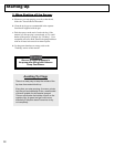
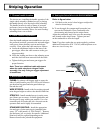
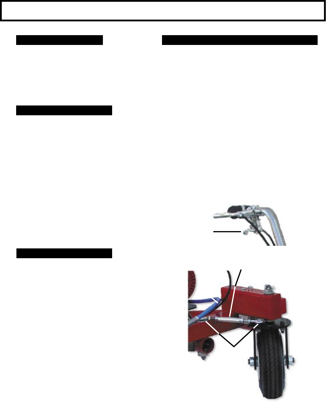
4. Setting the Swivel Wheel with RADIUS MEMORY
™
Refer to gure below
a. Pull back on the swivel wheel trigger to adjust the
wheel to desired angle.
b. To set the angle for constant arch loosen the jam
nuts on the Turnbuckle. Place Turnbuckle onto
the mounting nub located on the striper frame.
Adjust the turnbuckle until it ts over the mounting
nub located on the wheel frame. Tighten jam nuts
on the turnbuckle to af x the length.
Note: If you have archs that you paint regularly, purchase
additional Turnbuckles (P.N. 136-163) and keep them set to
those arc sizes for easy use.
Mounting Nubs
Turnbuckle
Wheel Release