


Page 19
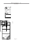
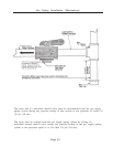
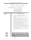
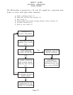
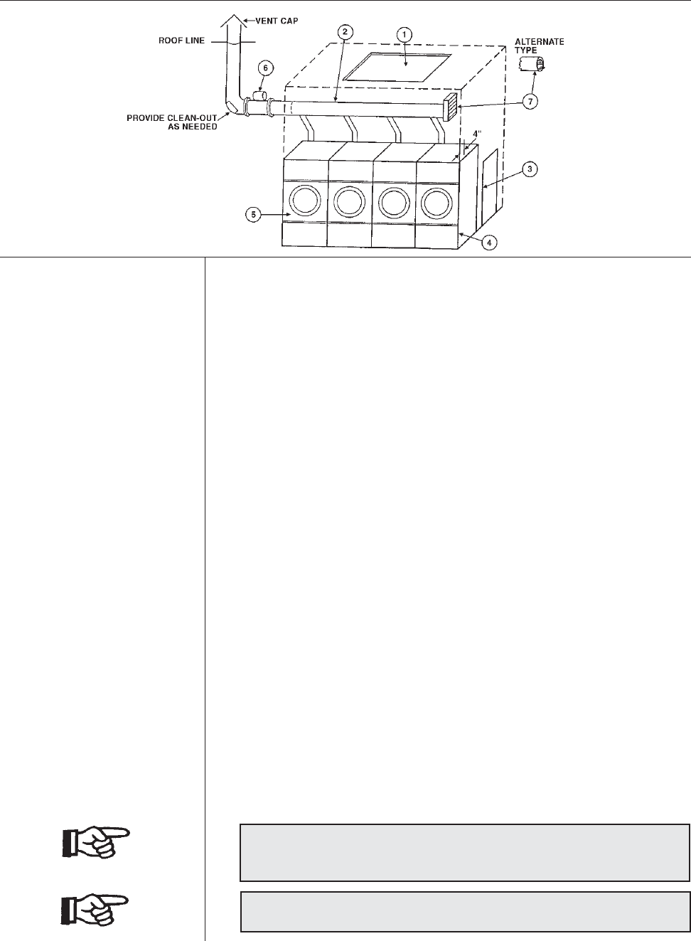
Dryer Installation with Multiple Exhaust
For Exhaust Duct more than 14 feet (5 m) and 2 elbows equivalent
and more than 0.3 inches (8 mm) static pressure.
(See illustration on page 21.)
1. Make-up air from outside building may enter enclosure from top
or side walls. (See Dryer Make-Up Air Chart)
2. Use constant diameter duct with area equal to the sum of dryer
duct areas.
EXAMPLE: Six 8 inch (204 mm)) diameter duct = one
19.6 inch (498 mm) diameter duct in area. Use 20 inch (508 mm)
diameter duct or diameter to match tube-axial fan.
3. Enclosure (plenum) with service door. This separates the dryer
air from room comfort air. If dryers use room air instead of
outside air, the heat loss can be another 25 Btu/h (6.3 kcal/h) for
each cubic foot per minute (cfm) used.
4. Zero inches clearance to combustible material allowed on sides
and at points within 4 inches (102 mm) of front on top.
5. Heat loss into laundry room from dryer fronts only is about 60
Btu/h per square foot (15 kcal/h per 0.1m²).
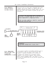
6. Flange mounted, belt driven tube-axial fan. Fan must run when
one or more dryers are running. See suggested Automatic
Electrical Control Wiring Diagram on previous page. Must meet
local electrical codes. Fan air flow (cfm) (m³/min.) is equal to sum
of dryer air flows, but static pressure (SP) is dependent on length
of pipe and number of elbows.
7. Barometric bypass damper—adjust to closed flutter position with
all dryers and exhaust fan running. Must be located within
enclosure.
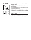
CAUTION: Never install hot water heaters or other gas
appliances in the same room as dryers. Never install cooling
exhaust fans in the same room as dryers.
CAUTION: Never exhaust dryers with other types of
equipment.
DRYER INSTALLATION
WITH MULTIPLE
EXHAUST