


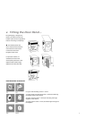
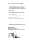

Fitting the Door Panel and Plinth...
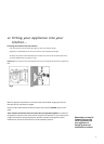
Mounting parts onto the face of the appliance:
-
Mount the hinge supports onto the face of the machine,positioning the hole indicated by
the arrow,in Fig.1,towards the inside of the face and using the type C screws.
- Mount the magnetic plate on the opposite side,at the top,using the two type B screws.
- Place the spacer illustrated in Fig 4/B between the machine front and the magnet receiver.
Using the drilling template:-
Proceed as follows when applying the panel to the appliance:
- To trace the positions of the holes on the left hand side of the panel, align the drilling
template to the top left side of the panel,using the lines traced on the extremities as a
reference.
- To trace the positions of the holes on the right hand side of the panel, align the drilling
template to the top right side of the panel.
- Use an appropriately sized router to mill the holes for the two hinges,the rubber plug and
the magnet.
Mounting the parts onto the wooden door panel:-
- Insert the hinges into the holes (NB.the movable part of the hinge must be positioned
facing away from the panel) and fasten them with the 4 type A screws.
- Insert the magnet into the top hole on the opposite side of the hinges and fasten it with
the 2 type B screws.
- Insert the rubber plug into the bottom hole.
- The panel is now ready to be mounted onto the machine.
Mounting the panel onto the machine:-
- Insert the nib of the hinge (indicated by the arrow in Fig.2) into the hole for the hinge and
push the panel towards the front of the machine. Fasten the two hinges with the type D
screws.
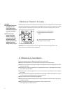
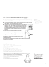
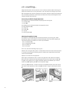
Fastening the plinth guide:-
If the machine is installed at the end of a set of modular cabinets,mount either one or both of
the guides for the base moulding (as shown,Fig.6).
Adjust them for depth,based on the position of the base moulding and if necessary fasten the
base to the guides (Fig.7).
This is how to assemble the plinth guide (Fig.6).
- Fasten angle P using screw R,insert plinth guide Q into the special slot and once it is in the
desired position,lock it in place using angle P and screw R.
8
Fig.6
Fig.7